I've started my own CW Keyer/Decoder project based on a BlackPill STM32F401 module because I'm not very good at Morse code (neither transmitting nor receiving) and I wanted something more sophisticated as an aid.
There is a similar more mature nanoKeyer project which is a CW keyer based on the Arduino platform and can be operated with a PS/2 keyboard or a Iambic paddle but has only a very limited decoder as an option.
By taking advantage of cheap modules available on Aliexpress I propose the following schematics for a BOM of around 15$
The design uses:
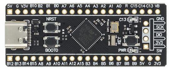
- a BlackPill F401 module (which is most of the time cheaper than an Arduino board)
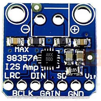
- an I2S speaker and up to 3W amplifier (MAX98357A)
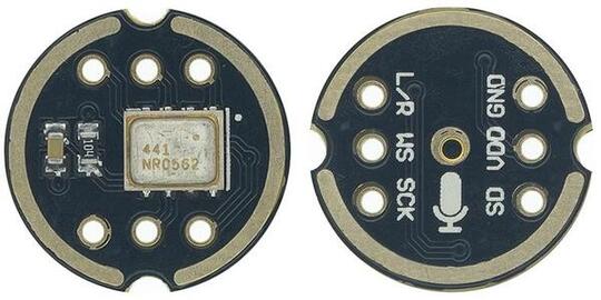
- an I2S microphone (INMP441)
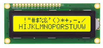
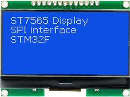
- a 16×2 alphanumeric or a 128×64 graphic LCD
- rotary encoder, buttons, switching supply, opto-couplers
Advantages:
- This design uses a modern Cortex-M4 84MHz processor with hardware floating point unit and lots of RAM.
- It can be a USB host so it will support modern (USB) computer keyboards. Typed keys will also be displayed on the LCD.
- The LCD allows parameter setting and the unit operates independent of computers.
- Connection and control from a computer is still possible via the USB-C connector present on the F401 module.
- The CW tone will be synthesized and the speaker will generate a pure sine wave which could be directly fed to the audio input or microphone of a SSB transceiver. Attack and decay envelopes of the sound will prevent popping noises. A CW output switch is also available.
- The I2S microphone will capture the ambient sound, apply a FFT transform and decode any captured Morse code (the display is split in transmit/decode mode).
- All the components are through-hole or modules and are easy to solder.
The project schematic
The device can be power from any 8-20V power supply and it is not wasting any power thanks to the GW1584 switching supply module. The small pot on that module needs to be adjusted for a 5V output prior to soldering all the components. I also put a drop of nail polish to permanently fix the output voltage. Alternatively the device can be powered from the USB-C connector of the CPU module from a power bank if you want to use it portable. You will need to use a USB-C cable without data lines (just 5V and Gnd) because the CPU has only one USB interface and it will conflict with the USB keyboard.
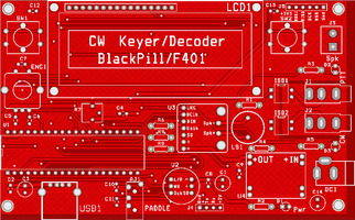
- Gerber files for PCB manufacture
2 layer PCB | |
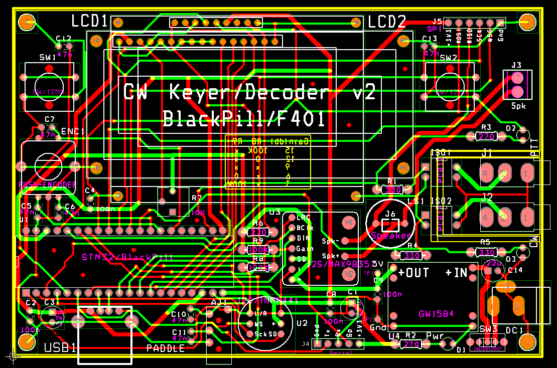 | 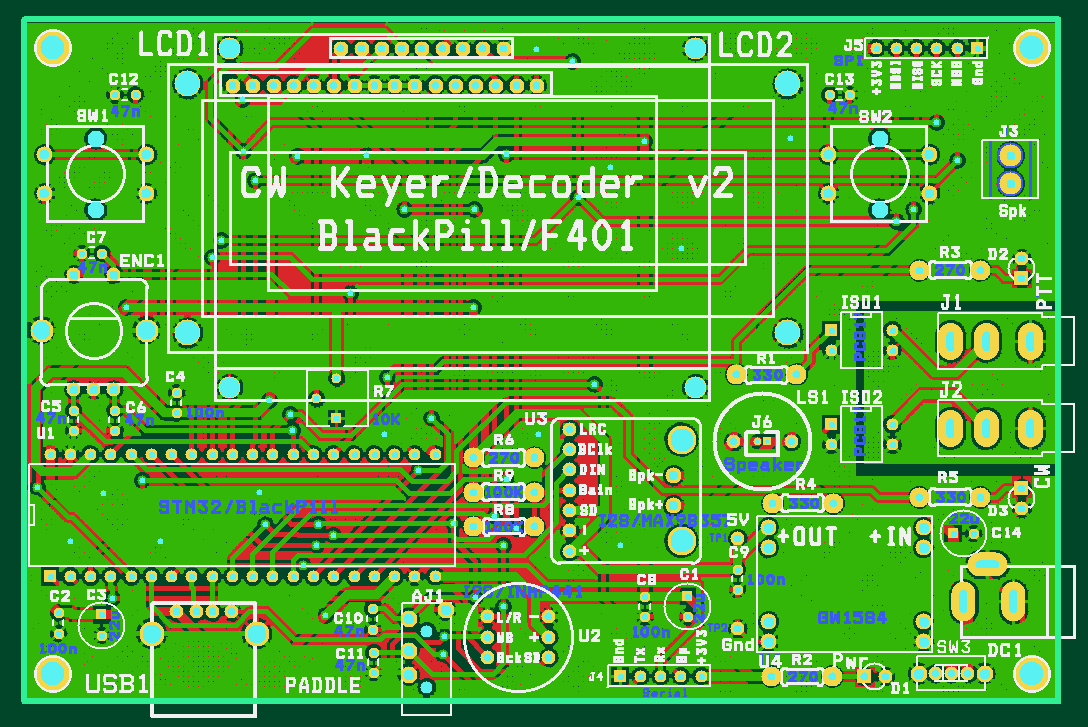 |
The PCB above is a second iteration of this project. I've changed the following:
- LCD is now powered from 5V instead of 3.3V. With 3.3V the contrast needed just a tad more even with the pot completely turned to Gnd level. By soldering an ICL7660 voltage doubler on the back of the LCD this can still be powered at low voltages and get a good contrast but then you loose the ability to adjust the contrast. If you only write to the display (which is the case) then the LCD can be powered at 5V while the CPU is driving it with 3.3V
- I've added a footprint for an SPI display. The CS line is shared with the 16×2 LCD enable line since one uses one or another. This allows the use of a SPI serial flash chip soldered on the back of the F401 module if more storage is needed (like animations or other graphics)
- I've added a switch on the power supply (you can use a wire if you don't need this)
Software
I've finished and released version 0.1 of the software. This version (written from scratch) completely suits my needs so let me know if you want any other feature added. Only the 16×2 LCD display has software support for now. The decoder uses a significant portion of the RAM but there is still plenty of memory available both in Flash and in RAM.
| Memory Resources: No Decoder |
 |
| Memory Resources: With Morse Decoder |
 |
The menus to change the different parameters (and their default values) are:
| Decoder Mode | Sidetone Volume | Sidetone Freq | WPM | WPM Farnsworth |
| Off | 45dB | 750Hz | 10 | 18 |
| Split | ||||
| Only |
| Keyer Mode | Sidetone Mode | Paddle Mode | Dah/Dit Ratio |
| Straight | Off | Normal | 3.0:1 |
| Bug | On | Reverse | |
| Single Paddle | Paddle Only | ||
| Iambic A | |||
| Iambic B | |||
| Ultimatic |
| PTT Lead Time | PTT Tail Time | Mem Repeat Time | Beacon Mem: F00 |
| 10ms | 3ms | 0.0s | - disabled - |
To program the firmware unplug the keyboard and connect the CPU with an USB-C cable to computer. While keeping the Boot0 button pressed reset the CPU and this will enumerate as a DFU device. Use the command bellow to program your device.
dfu-util -R -a 0 -D CW-Keyer_vXXX.dfu
I'm using Rowley Crossworks for development but the Makefile and linker ld file can be adapted for GCC only development. All development and source files are here.
The only relevant files are in the Core sub-folder, all the other are generated by CubeMX. The DSP sub-folder is a trimmed down version of the CMSIS DSP Library (v1.9.0) which is used to fast compute trigonometric functions and 64 points Complex FFT.
The program uses FreeRTOS and starts a few equal priority threads with no pre-emption just after the hardware initialization. The memory allocation is dynamic but this is only because the CubeMX USB host implementation cannot handle static allocation. I'm not explicitly allocating and freeing heap memory. There are no mutexes or semaphores, instead I'm using the much faster (and leaner on the resources) task notifications.
In addition to USB keyboards all of the following keyers are supported: Straight key, Bug, Single paddle, Iambic A/B and Ultimatic. They are plugged into the stereo 3.5mm jack and the dit/dah lines can also be swapped if wanted. While transmitting with a keyer the time intervals of the clicks are used to decode in real time what is transmitted. The transmission speed can be adjusted in WPM or using Farnsworth WPM. Lead and tail delays can be added for PTT activation.
When using the keyboard the keys are pushed on the right side of the display and stored in a buffer. The cursor will blink under the character which is currently transmitted.
Short phrases which are used often are stored in the flash memory and can be played back with the F1-F12 keys from the USB keyboard. There is also a beacon mode where a chosen phrase is transmitted autonomously at an adjustable time interval.
Reading the encoder and the on-board switches uses a 500Hz timer interrupt. The frequency needs to be this high to catch fast encoder movements. Mechanical debouncing is observing the past 8 samples (8 / 500Hz = 16ms) to detect valid transitions.
For sidetone generation a sine wave is computed every time the frequency or the amplitude is changed. At the same time a number of decreasing amplitude sine waves are also computed. These are needed to be played back at the end of a sidetone to prevent an annoying popping sound. The playback uses the I2S peripheral in DMA mode with a double buffer configuration and 16KHz audio rate. When the sidetone ends the alternate buffer is pointed to the decreasing amplitude versions of the tone.
All the configuration options and phrases are kept in the first sector of flash. I've chosen the first rather than the last because it has a smaller size of only 16KB instead of 128KB and even 16KB is way too much for options. Since it is the first sector at address zero I need to write the first 0x30 bytes every time I erase this sector (which is not often) with a small bootstrap code which passes execution at 0x8004000 where the code resides. There are two regions in this first sector, one for saved strings and one for options. Every time an option is changed and saved a new copy of the options structure is written to the flash. Once the program runs out of options space it will erase the entire sector, reset the strings and copy only the last used options structure.
Morse Decoding
To decode incoming Morse code the digital microphone is activated and sampled at 16KHz. The data is also acquired using a double buffer DMA mode and while one buffer is filled the other one is processed. The CubeMX provides no support for double buffer I2S capture (there is support for double buffered DMA but not for the I2S interface) so I had to write my own.
The microphone samples are 24bit mono and every second one is zero. The 32bits of the mono samples have to be swapped (because the I2S/SPI peripheral is 16bit) and also right aligned. The samples are then transformed to floating point because the amplitude can vary a lot and I'll perform the FFT on complex floating point numbers since the CPU has a hardware FPU and is fast. It would have been great if I could have done these transformations in place but while the buffer in under DMA control (even while not actively written) you cannot change its content so I had to use a separate buffer for the FFT (another half kilobyte of RAM wasted).
By using FFT on complex floating point numbers the decoding works for CW tones regardless of their frequency or amplitude.
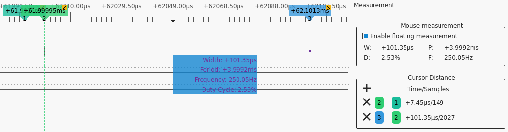
I was impressed of how fast the FFT and transition detection is done as you can see in the logic analyzer capture bellow. Once one buffer is filled the interrupt sends a notification. The decoding thread then starts 8us later and after just about 100us the FFT largest magnitude and transition are recorded. There are 3900us until the next frame so there is plenty of time to serve all the other threads.
DFT Timing
Bellow you can see the tone (and bin) detection for a typical Morse reception.
DFT
Detecting Morse symbols from tone transitions is not trivial. The best would be a class segmentation algorithm which will group the on and off intervals in classes. This is computational intensive and I haven't tried it yet. Instead I'm relying on the fact that the dit/dah ratios are approximately 1:3. When a Iambic or Ultimatic keyer is used then the space intervals ratios are also approximately 1:3. Sorting the intervals and using these ratios works reasonably well in the get_dit_dah_timing function but this could be further improved.
I keep all previous magnitudes and transition in 4096 long buffers (16KB + 0.5KB of RAM) so the last 16 seconds of Morse reception are available for decoding. The algorithm adapts while it receives more symbols and can correctly decode and display even past symbols. This is also the case when the WPM speed changes when tuning to another station. When using computer generated Morse code the decoder works with no errors to speeds up to 50WPM. With human operators the decoding is less accurate but still quite good (and it can be improved in software). I've tried some Morse decoding apps on smartphones and they are not better than this decoder. The decoder is very flexible and doesn't need any adjustments for WPM transmission speed, amplitude or tone frequency.
The STM32F401 processor CubeMX and its documentation
Components | |||
 | ARM Cortex-M4 STM32F401xC.pdf | 5pcs | $17.58 |
 | LCD1 16×2 lines | 5pcs | $11.82 |
 | or SPI LCD2 128×64 pixels | 5pcs | $20.35 |
 | I2S Microphone INMP441.pdf | 5pcs | $10.04 |
 | I2S Speaker Amplifier MAX98357A.pdf | 5pcs | $12.92 |
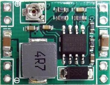 | Switching Power Supply MP1584.pdf | 5pcs | $3.95 |
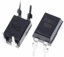 | Opto-coupler PC817.pdf | 20pcs | $2.28 |
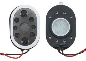 | Speaker 1.5W 8Ohm 20×30mm | 5pcs | $4.96 |
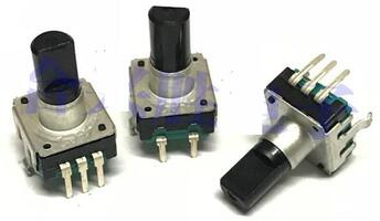 | Rotary Encoder | 5pcs | $2.88 |
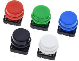 | Switch with Caps 12×12mm | 25pcs | $2.38 |
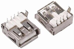 | USB Type A Socket | 10pcs | $1.52 |
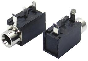 | PJ316 3 pin Socket | 10pcs | $1.87 |
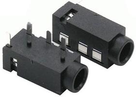 | PJ320a Stereo Socket | 100pcs | $6.03 |
 | PCB 1.6mm 2 layers | 5pcs | $15.20 |
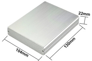 | Aluminum Enclosure | 4pcs | $40.73 |
| Total | $133.88 | ||
The components cost (with shipping) for one CW keyer including the PCB and the aluminium enclosure is around 25$ (or 15$ without the enclosure).