The Malahit (Malachite) SDR is a very compact radio hosted in an aluminium case only 100×74×27mm in size.
The version I've bought is manufactured in China but the design
originated from Russia. The schematic is almost identical to the
original except
some PCB connectors (J5 & J7). The RF front-end is minimal, just a wideband
pre-amp (BGA614) and some LC Π
filters (0-12MHz-30MHz-60MHz-120MHz-250MHz-1GHz-2GHz) to separate the huge
frequency range. An
optional board
with better filtration and another narrower pre-amp for the HF bands can be
connected via J7 and is inserted in front of the antenna connector. On this
chinese clone the Vbat signal is missing so you need to connect it from
elsewhere (and there isn't sufficient space inside the case for another PCB
anyways).
A translated manual is
also available.
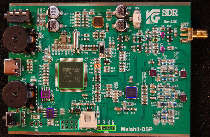
A few things that I dislike on this SDR:
- the touchscreen is resistive, imprecise and it struggles to register presses
- the encoder wheels often skip increments (badly written software)
- the 22MHz oscillator frequency drifts especially after power on
- the speaker is on the back so you cannot lay the SDR on a desk because the sound will be completely muffled
Even with the above annoyances I think it is an excellent deal to get a portable SDR in an aluminum case for just 82$ delivered.
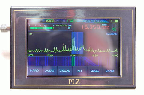
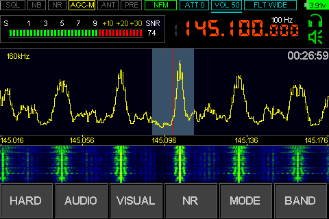
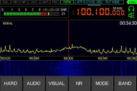
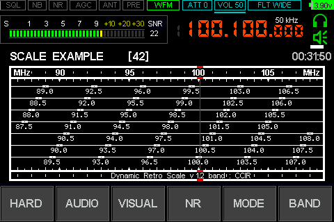
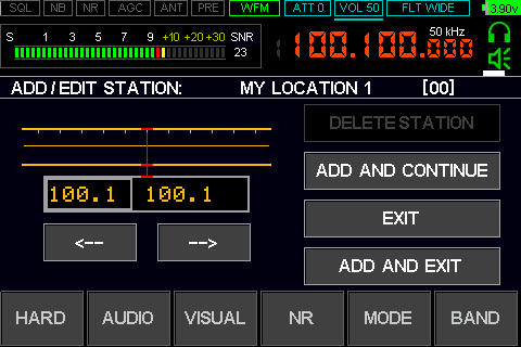
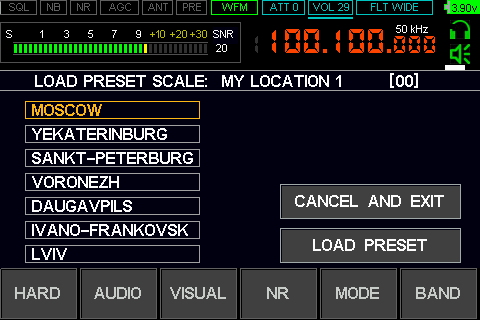
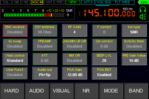
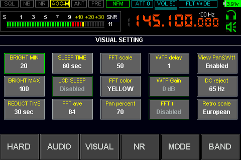
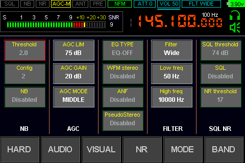
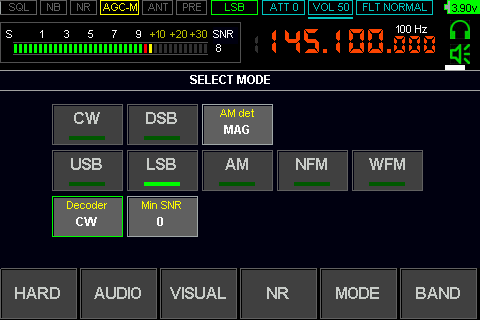
Screen Captures (FW_1_10c)
| 
|
| 
|
| 
|
| 
|
| 
|
There are 2 versions of the NAU8822 audio CODEC chip (A and L). The difference between them is that the 'L' has an extra bit in the PLL registers to select the PLL output frequency divided by 2 instead of only 4 in the 'A' chip.
| NAU8822A/L Master Clock | |
The master clock MCLK has to be exactly 256 times higher than the sampling rate. The PLL inside the NAU8822 only locks between 90-100MHz. The maximum sampling rates when using the PLL are:
- 100MHz / 4 / 256 = 97.6kHz for the 'A' chip
- 100MHz / 2 / 256 = 195.3kHz for the 'L' chip
The only way to increase the sampling rate is by not using the onboard PLL and provide the MCLK from the STM32 PLLs (which has plenty). For a 160kHz sampling rate you need a 40.96MHz clock. You can get that if you program the fractional PLL2 in the STM32: 22MHz / 2 * 69 / 9 and a fracn2 of 209 to 81.92MHz and with another division by 2 in the SAI1 peripheral you can get exactly the desired MCLK. Now the question is how well is the PCB track laid and shielded to carry a 40MHz clock and also will the ADCs and DACs in the older NAU8822A work with an almost 4 times higher sampling rate.
The waterfall bandwidth can be selected between 160kHz, 80kHz and 40kHz so I presume the master clock is adjusted accordingly. If you experience audio quality problems with the NAU8822A chip you can just reduce the displayed bandwidth. Alternatively the NAU8822L chip can be purchased from Aliexpress for very little (I can confirm that the linked seller sent me the 'L' version as listed). Replacing it (QFN32 package) is quite an easy task using just a hot air rework station.
Radio Firmware
In main() inside the main program loop there is this:
GPIOA_MODER &= 0xF3F3FFFF;
which makes PA13 (SWDIO) and PA9 (OTG_FS_VBUS) inputs, effectively
interrupting any ongoing debug session.
I don't know if this was deliberate or just a programming mistake.
To be able to debug and breakpoint the firmware I've replaced it with:
GPIOA_MODER &= 0xFFF3FFFF;
You can see here the convoluted way the encoders are read: File: encoders.c
uint8_t       encoder_1or2, encoders_conf;
uint32_t      encoder_mode[2];
int32_t       encoder_val[2];
const int8_t  encoder_deltas[16] =
    { 0, -1, 1, 0, 1, 0, 0, -1, -1, 0, 0, 1, 0, 1, -1, 0 };

// the encoders function is called from EXTI_Int 0-3

int
encoders( int bit_enc )
{
  int           PC_b1b0;
  int           PC_b3b2;
  int           delta;
  int           result;

  switch ( encoder_1or2 )
  {
    case 0:
      PC_b1b0 = GPIOC->IDR & 3;
      if( encoders_conf & 1 )
      {
	delta = PC_b1b0 + 4 * encoder_mode[0];
	encoder_mode[0] = PC_b1b0;
	result = encoder_val[0] + encoder_deltas[delta];
	encoder_val[0] = result;
      }
      else
      {
	delta = PC_b1b0 + 4 * encoder_mode[0];
	encoder_mode[0] = PC_b1b0;
	result = encoder_val[0] - encoder_deltas[delta];
	encoder_val[0] = result;
      }
      return result;
    case 1:
      PC_b3b2 = ( GPIOC->IDR >> 2 ) & 3;
      if( encoders_conf & 2 )
      {
	delta = PC_b3b2 + 4 * encoder_mode[1];
	encoder_mode[1] = PC_b3b2;
	result = encoder_val[1] + encoder_deltas[delta];
	encoder_val[1] = result;
      }
      else
      {
	delta = PC_b3b2 + 4 * encoder_mode[1];
	encoder_mode[1] = PC_b3b2;
	result = encoder_val[1] - encoder_deltas[delta];
	encoder_val[1] = result;
      }
      return result;
  }
}

// horrendous coding from now on:
// every 6 SysTick interrupts process_encoders is called
// this is some kind of averaging over the last 4 values

uint32_t encoder_last4[8];
uint32_t encoder_update[2];
uint32_t last_4_pos[2];
int      encoder_sgn_dbl[2];
int      encoder_rem[2];

void
process_encoders( void )
{
  int idx;
  if( encoder_1or2 )
  {
    idx = last_4_pos[1] + 4;
    encoder_sgn_dbl[1] += 2 * encoder_val[1];
    encoder_last4[idx] += abs( encoder_val[1] );
    encoder_update[1]++;
    if( encoder_update[1] )
    {
      encoder_update[1] = 0;
      last_4_pos[1]++;
      last_4_pos[1] &= 3;
      encoder_last4[4 + last_4_pos[1]] = 0;
    }
    encoder_val[1] = 0;
  }
  else
  {
    idx = last_4_pos[0] + 0;
    encoder_sgn_dbl[0] += 2 * encoder_val[0];
    encoder_last4[idx] += abs( encoder_val[0] );
    encoder_update[0]++;
    if( encoder_update[0] )
    {
      encoder_update[0] = 0;
      last_4_pos[0]++;
      last_4_pos[0] &= 3;
      encoder_last4[0 + last_4_pos[0]] = 0;
    }
    encoder_val[0] = 0;
  }
}

int
i_read_encoders(uint32_t *average, signed int divider, int encoder_nr)
{
  uint32_t *last4;
  unsigned int v1, v2;
  int enc;
  int result;

  last4 = &encoder_last4[4 * encoder_nr];
  v2 = 0xf00 * (encoder_update[encoder_nr] + 3);
  v1 = 80000 * (*last4 + last4[1] + last4[2] + last4[3]);
  enc = encoder_sgn_dbl[encoder_nr] + encoder_rem[encoder_nr];
  encoder_sgn_dbl[encoder_nr] = 0;
  *average = v1 / v2;
  result = enc / divider;
  encoder_rem[encoder_nr] = enc % divider;
  return result;
}

uint32_t encoder_clicks[10] = { 20, 30, 10, 20, 5, 15, 2, 10, 1, 6 };
uint32_t var_is_4 = 4;

// finally when the code wants to read an encoder value it calls read_encoders

int
read_encoders(int *clicks, int encoder_nr)
{
  int result;
  signed int select;
  uint32_t average;

  result = i_read_encoders(&average, var_is_4, encoder_nr);
  if ( average > 0x1D )
    select = 0;
  else if ( average > 0x13 )
    select = 1;
  else if ( average > 0xE )
    select = 2;
  else if ( average > 9 )
    select = 3;
  else
  {
    if ( average <= 5 )
    {
      *clicks = 1;
      return result;
    }
    select = 4;
  }
  *clicks = encoder_clicks[2 * select];
  return result;
}

// all of the above to read two encoders ...
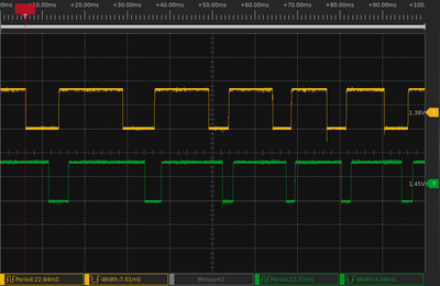
| Encoder A/B Line Captures | |
| 
|
| 
|
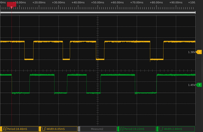
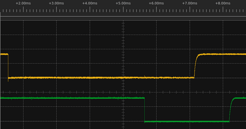
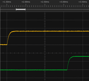
After hooking a scope to the encoder outputs I was surprised how clean the
signal was. There was no noise at all on the contacts. Rising edges were as
calculated and the falling edges perfectly sharp (less than 100ns).
This leaves just the software to blame.
The proper way to read an encoder is to generate an interrupt on the falling
edge of one input (for steps) and then in the interrupt read the other input
value (and that gives you the direction).
I have replaced the encoders code with a cleaner version:
encoders_fixed.c
and my encoders behave better now work exactly as they should
they still don't register all the clicks. and don't miss any clicks.
The hardware debouncing RC constant is given by the port
pull-up resistor (40K) and the 1nF capacitor and that gives only 30us (way too
low, should be in the ms range).
I've fixed another bug that was driving me crazy: sometimes the radio was waking up by itself (and completely draining the battery). This was happening after about 10 seconds of turning the radio off. I was looking for missing or to weak pull-ups but it was something in the firmware.
The watchdog IWDG is enabled and in the main loop you have to write to it
more often than 10 seconds or your CPU will reset.
When you shutdown the radio there is no way to disable the watchdog
once it has been started but you can freeze its counter when entering standby mode.
In main():
- program bit IWDG_FZ_SDBY in FLASH->OPTSR to freeze watchdog counter in standby
- program BOR bits in FLASH->OPTSR for VBOR2 (2.3V)
- program bit WDGLSD1 in DBGMCU->APB4FZ1 to stop watchdog in debug mode
The shutdown steps are:
- save all the relevant variables in FRAM
- play "73" in Morse code
- reprogram the IWDG to 500ms and also request a reset by setting the SYSRESETREQ bit in SCB->AIRCR
- after the reset (whichever of the above happens first) the watchdog is disabled
- before the main loop check the battery voltage to see if early low power mode is needed
In low power mode:
- disable all peripheral clocks and interrupts
- enable the wakeup interrupt (PC13) as the only source for power on
- program PWR->CPUCR and select Standby (not Stop) for D1,D2,D3 domains in DEEPSLEEP mode
- set the DEEPSLEEP bin in SCB->SCR and end with 'wait for interrupt' __wfi()
All of the above works fine except when you put the chip in debug mode. In the debug session the watchdog is disabled but when the CPU goes into standby mode then the IWDG_FZ_SDBY bit has no effect, the watchdog is still enabled (this is a bug in silicon) and it will wake the radio up after 10 seconds. Resetting the chip or disconnecting the STLinkv2 wires doesn't help. The chip stays in this mode until you power it down (disconnect the battery).
There is a long discussion on the STM32 forum with people not being able to freeze the watchdog in shutdown or standby modes. From there I've got the suggestion of resetting the MCU debug control register before entering DEEPSLEEP mode and that worked. I have changed the 'low_power_mode' function and inserted one instruction before its end:
  DBGMCU->CR = 0; // workaround: add this instruction before entering DEEPSLEEP
  SCB->SCR |= 4;
  __dsb();
  __isb();
  __wfi();
Another way to make sure your watchdog is always stopped is to put a flag in the backup memory and then after the reset but before enabling the watchdog, test that flag and enter DEEPSLEEP if required.
This bug has now been fixed in the original firmware since version 1.10c rev2
The code never resets the backup domain and that survives CPU resets and even firmware updates. The only way to reset the backup domain is by removing the battery (the voltage on Vbat) or by setting bit 16 in RCC->BDCR register to set all backup registers to default. The firmware doesn't write to the RTC->CR register and bit 10 in this register is the wakeup timer interrupt enable. If this bit happened to be set then you will get a wake-up signal every RTC->WUTR ticks and this could also wake up the radio.
I've re-written the RTC code. I disable all the RTC interrupts and also use a more recent default date for the calendar. rtc_fixed.c
You can use this STM32CubeMX project file as a starting point you you want to write your own software for the platform.

To obtain the flash binary file first remove the RAM fill region (starting with line ':020000043002C8') and the reset address (the line before last) which are not part of the image. If you don't remove the RAM region your converted binary file will also contain the gap between the end of the flash and the start of SRAM2 and this will make the size of your converted file hundreds of MBytes.
For conversion, the easiest way is to use objcopy:
objcopy --gap-fill=0xff -I ihex FW_xxxxx.hex -O binary FW_xxxxx.bin
To program a new firmware in DFU mode:
- connect the USB cable and turn radio off
- press and hold the encoder button (the one opposite to the power switch)
- turn the radio on and then release the encoder button (the screen will stay black)
- if you have a corrupt firmware and the above doesn't work you'll have to
bridge the JP1 jumper to force DFU mode while you program your device - in linux you can check that the CPU is in DFU mode with 'lsusb' command
Alternatively you can use the SWD interface to program the CPU much faster. The SWD also allows you to debug, inspect, dump memory, screen captures etc.
Convert between iHEX and binary formats (ihex2bin / bin2ihex / stm2ihex / stm2ihex.exe / C source code ) then use:
dfu-util -R -a 0 -s 0x8000000 -D FW_xxxxx.bin
or convert to DFU (hex2dfu / hex2dfu.exe / C source code) then use:
dfu-util -R -a 0 -D FW_xxxxx.dfu
I prefer to use the SWD port directly. For this you need a STLinkv2 programmer. The SWD connector on the board misses the 3V3 power rail but you can get that from the common anode dual LED (near TP4056 charger which is not soldered). The 3V3 is needed to detect the Vtarget presence. If you use a STLinkv2 clone (the USB stick shaped one) you won't have the Reset signal available (the one labeled RST is from the SWIM interface). Reset is available on port PB0 (pin18 of STM32F103) inside the programmer. Without Reset you'll have some trouble halting the STM32H7.
Start openocd:
openocd -f interface/stlink.cfg -f target/stm32h7x.cfg -c "reset_config connect_assert_srst"
open a telnet console:
telnet localhost 4444
and then issue the following commands:
    reset halt
    ### flash read_bank 0 backup.bin 0 0x100000 (if you want to save your current firmware)
    flash erase_address 0x8000000 0x100000
    flash write_bank 0 firmware.bin 0
    reset
to program your new firmware.
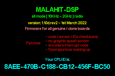
The firmware for this radio (version 1_10a at end of Jan 2021) needs to be first activated.
The registration code is an 8 byte hash of the CPU signature ID (12 bytes).
This hash is then stored at (word) locations 0x7E & 0x7F in the SPI F-RAM
(FM25W256)
and compared every time the radio is powered on.
Starting with version 1_10b all the ID hashes (actually a hash
of the hash) issued by the author are stored in firmware
(just a little under 1000 at the time of the writing).
The activation code algorithm remains the same, but the radio (deliberately)
malfunctions if your code is not in that list.
This means the author has to generate new firmware images every few days after
new registrations.
Starting with version 1_10c activation codes are not used any more.
You have to send your CPU ID to the author and he will include a hash of that
number in the new released firmware (1600 registrations by now).
This leaves users with 3 choises:
- Purchase a registration from the author and wait a few days
- Stay with version FW_1_10a (google for it) and generate your own code bellow
- Patch the flash image if you have the know-how:
This involves patching the code to "find" your hash in that list.
There are also 6 regions (including code) plus the splash screen plus the hash IDs table which are checksummed.
I can't patch it for you because I'm not allowed to distribute other people's firmware (modified or not).
To unlock (activate) your Malahit SDR firmware (only up to FW_1_10a) please enter the CPU ID code
Use this format xxxx-xxxx-xxxx-xxxx-xxxx-xxxx (where x are hex nibbles)
