RGB Matrix Clock
9th August 2014

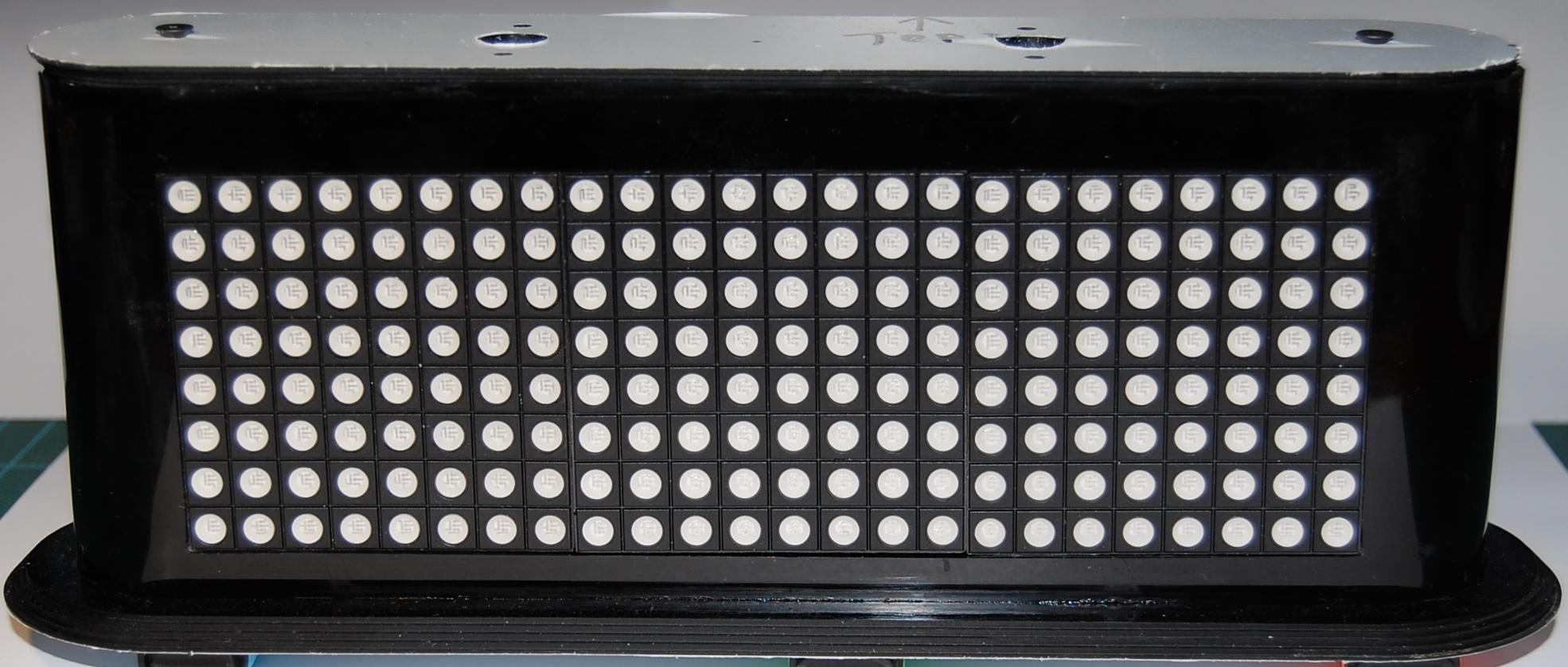
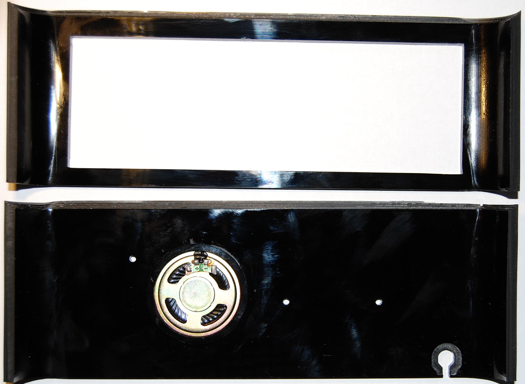
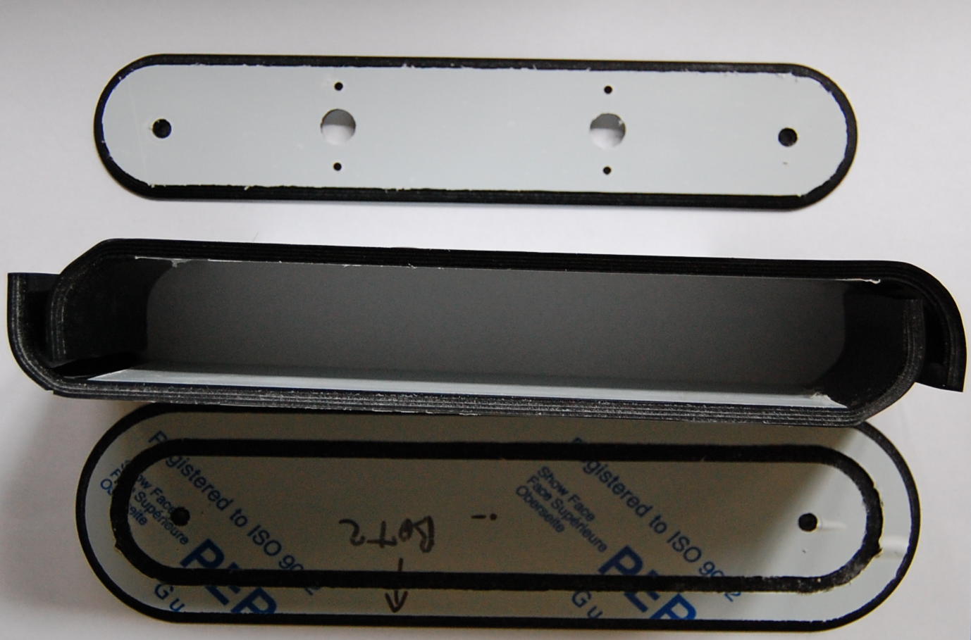
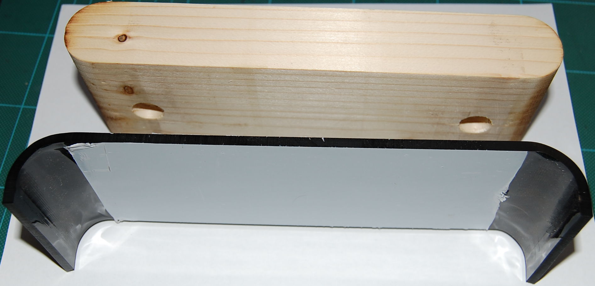
This is an example of over-engineering: a clock with 4 microcontrollers! Three of these are ATmega368 which are part of a cheap development board the Colorduino. Each of these controls one third of the display namely one 8×8 RGB LED matrix. The synchronization and communication between these 4 microcontrollers will happen via a multi-master I2C bus. So far I've finished the case and I've written a simulator in GTK of the various display modes which you may download bellow.
| Clock simulator | 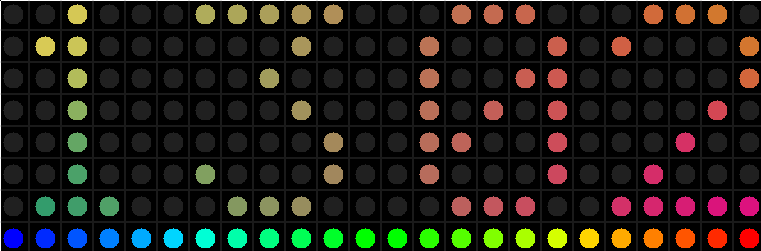 | |
| Linux version | Windows version and GTK runtime | |
| DXF design file (QCAD) | ||
Here is the Colorduino schematic of one Colorduino module.
The RGB clock schematic and Gerber files.
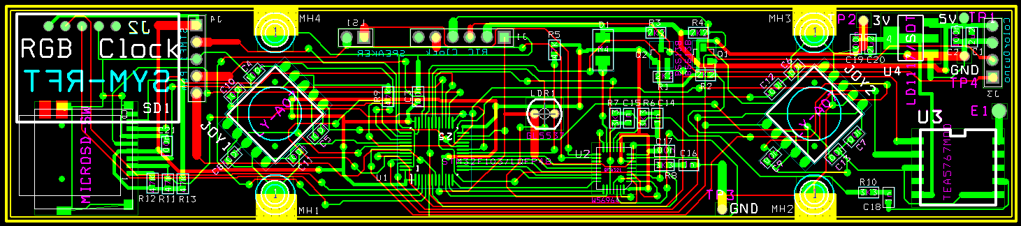 |
| Main PCB |
 |
| Caption |
 |
| Caption |
 |
| Caption |
 |
| Caption |
| Caption |
| Caption |
 |
| Caption |