I've recently bought online a large quantity of displays and paid a very good price for the lot. The displays came "as is" with absolutely no documentation or hint from the web. The company that originally produced them was out of business and their website was gone. I hopped that I will be able to reverse engineer these displays and my work paid off.
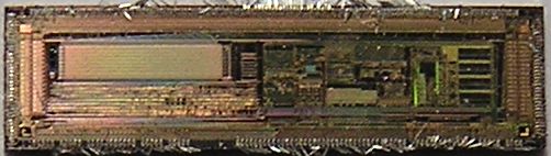
First of all I've decapsulated the display controller (using nitric acid heated at 70 degrees) and then I've took pictures of the die using a Nikon Optiphot microscope.
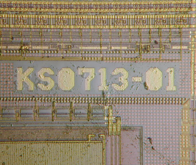
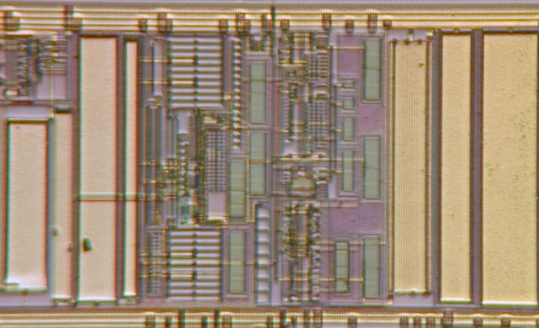
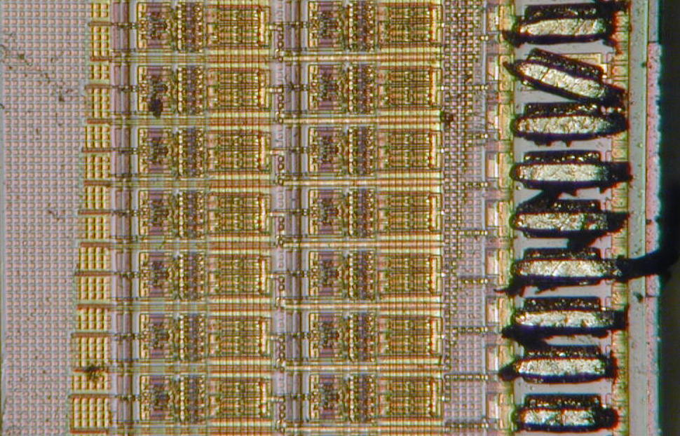
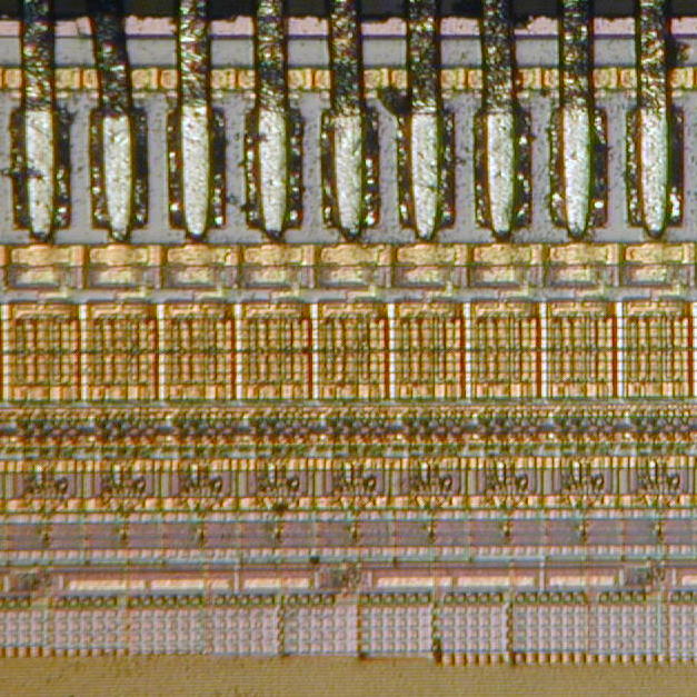
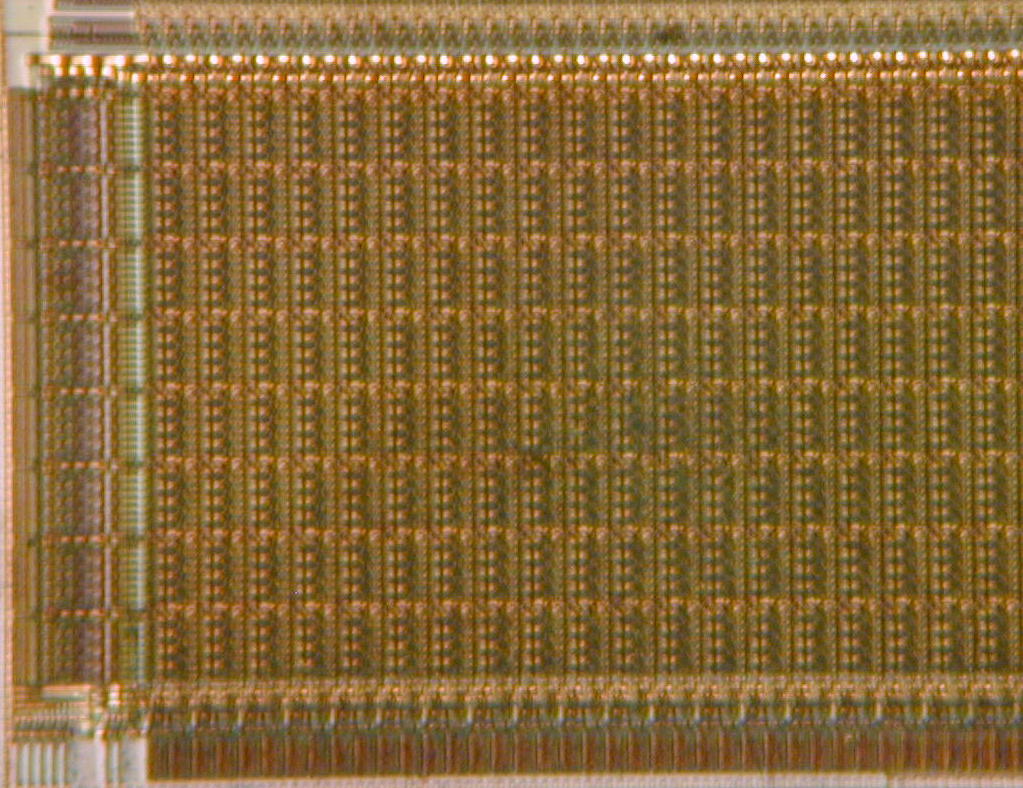
The following images show different shots of the KS0713 controller.
The die marking and the analog circuitry to multiply the voltage
The LCD segment drivers
The LCD static memory (twice the display size)
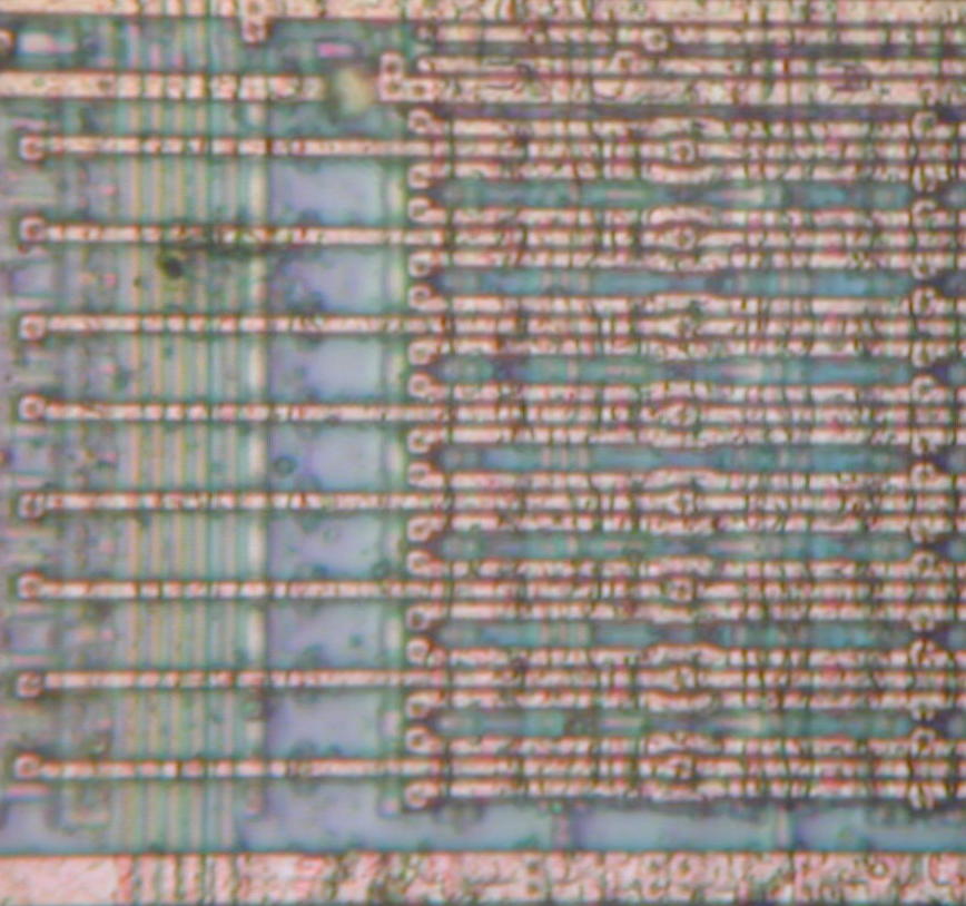
The die marking immediately pointed out to the Samsung datasheet for the controller KS0713 and for one of its close relatives S6B1713.
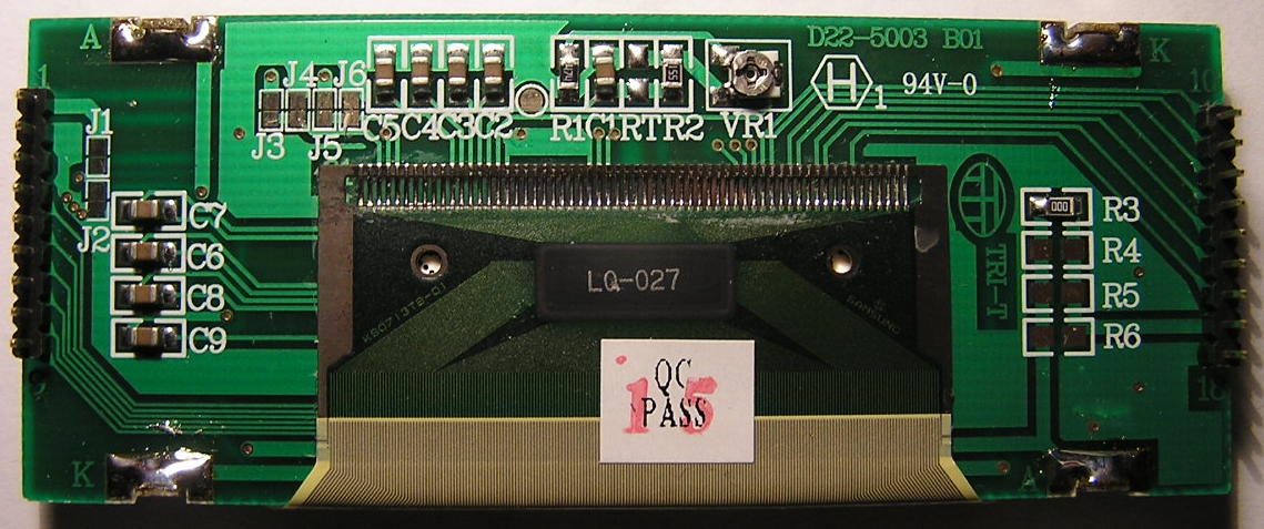
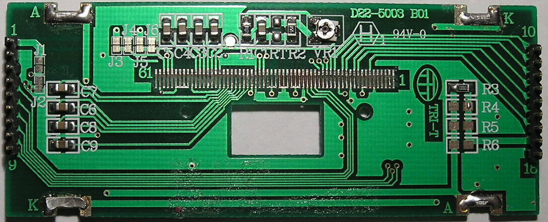
Then I have reversed the PCB schematic to find out the controller's hardwired operating modes. Notice that there are 3 pairs of jumpers on the PCB if you ever need to change the display behaviour.
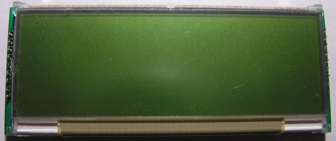
If you plan to use the (green) backlight you need a higher voltage power supply (min 8.1V) otherwise the LEDs won't work. You can modify the LEDs series resistors directly on the PCB by replacing R3-R6. Turn VR1 anti-clockwise if you want to increase the LCD contrast. The picture bellow shows the display without backlight so you can see the contrast is quite good in normal light.
The controller's memory is twice the display size. This means you can set a pointer in the RAM with one simple command to tell the controller which part of the RAM to display. This is handy for two reasons. One you can implement scrolling displays by updating only one (new) row of characters and then moving the RAM pointer. This saves a lot of time because you don't need to update the whole display each time you need a new row of characters. Secondly you can use the hidden memory as general purpose RAM for the microcontroller. There is enough space (528 bytes) to store a full NAND page including the spare area if your project uses this kind of nonvolatile memory.
The display can be mirrored both horizontally and vertically in software so you can position it any way you like.
I've used a STK500 Atmel development board to write the software with an ATMega16. If you use processors with parallel port modes (like the ATMega128 or even the PIC16F877) then writing data to the display is faster because you don't have to bitbang the latch signals. Here's an example of using the ATMega128 mapped memory:
  unsigned char *ks0713 = ( unsigned char * ) 0x1100;  // external memory
  XMCRB = 0x87;                 // Bus keeper, full port C
// XMCRA = _BV( SRW11 );       // extra delay
  MCUCR = _BV( SRE );           // enable external memory
//  MCUCR |= _BV( SRW10 );      // extra delay

You simply do then
	c = *ks0713 	or 	*ks0713 = c
if you want to read or write data to the display

The image you see on the display has been created with the following lines of code:
  show_icon( ( void * ) meter, 32, 32, 0, 0, LCD_PIXEL_ON ) ;
  draw_line( 44, 18, 44, 32, LCD_PIXEL_ON );
  draw_line( 34, 26, 132, 26, LCD_PIXEL_ON );
  for ( x = 34; x < 132; x++ )
  {
      y = 25 + 6. * sin( 2 * M_PI * (x % 23) / 22 );
      draw_point( x, y, LCD_PIXEL_ON );
  }
  draw_rectangle( 92, 18, 132, 34, LCD_PIXEL_ON, LCD_PIXEL_INV );
  select_font(( void * ) font_6x11, 6, 11 );
  draw_text( 34, 11, "Graphic display" );
  draw_text( 34, 20, "132 x 32 pixels" );
The program (library) includes functions to draw graphic primitives like points, lines (with Bresenham algorithm) and (filled or not) rectangles. By using the display in the parallel mode then pixel toggle is available because you can also read the display RAM. The math library is linked only because I used the sinus function. Otherwise only integer arithmetic is used and no special C library is required.
You can use and mix as many character fonts as you like provided you have enough space to store them in the microcontroller's ROM. Use select_font to choose the font and then display any text (with wrap around if the end of the display is reached) at the desired coordinates.
Graphic icons can be "pasted" from ROM to any screen location in normal or inverse mode or XORed with the current image.
The RAM is screen mapped in a vertical mode (bit0 up bit7 down). This is different from desktop computers which store their display information horizontally. Therefore I've included 2 conversion programs convert-font and convert-xbm which reencode the graphical patterns vertically before storing them into the uP's ROM. This saves a lot of cycles because the microcontroller only has to vertical shift the sprites (for aligning them to bytes) rather than shifting each pixel to form vertical bytes.
The library includes versions for both the parallel and the serial mode (just define or undefine PARALLEL_MODE in the C source). In parallel mode you need the full data bus (8 lines) and the control signals (5 lines). In serial mode only a serial bus (2 lines) and a reduced number of control signals (3 lines) are necessary. The serial mode saves pins on your microcontroller ports (making the display suitable for the 8 bit PIC series) but you cannot read the values stored in the display RAM (so you don't have the XOR overlay mode). Another minor disadvantage is the slower transfer speed.
You can download the full code and makefile here.