Emil's Projects & Reviews

OpenHardware & OpenSource

Making a better HC-SR04 Echo Locator 22nd January 2014

I have bought several cheap echo location circuits from AliExpress and I'm planning to use them in one of my robotics projects.
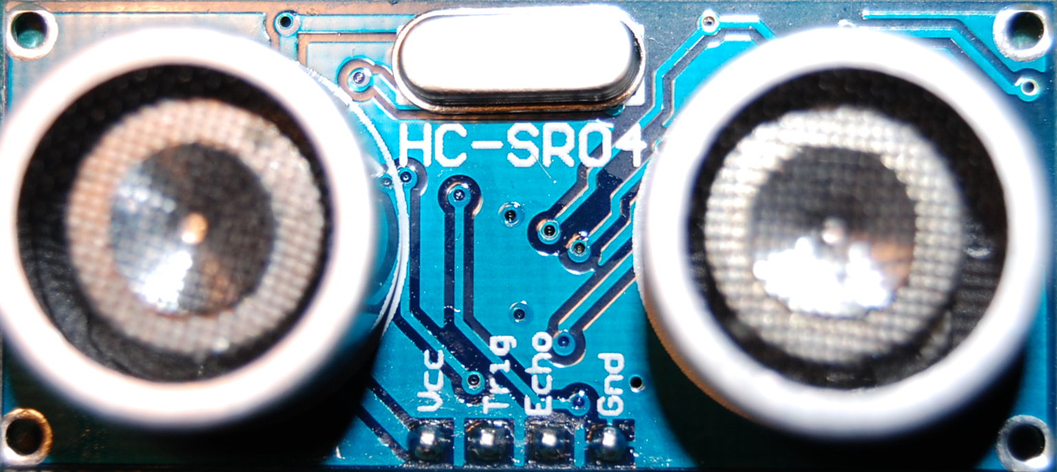
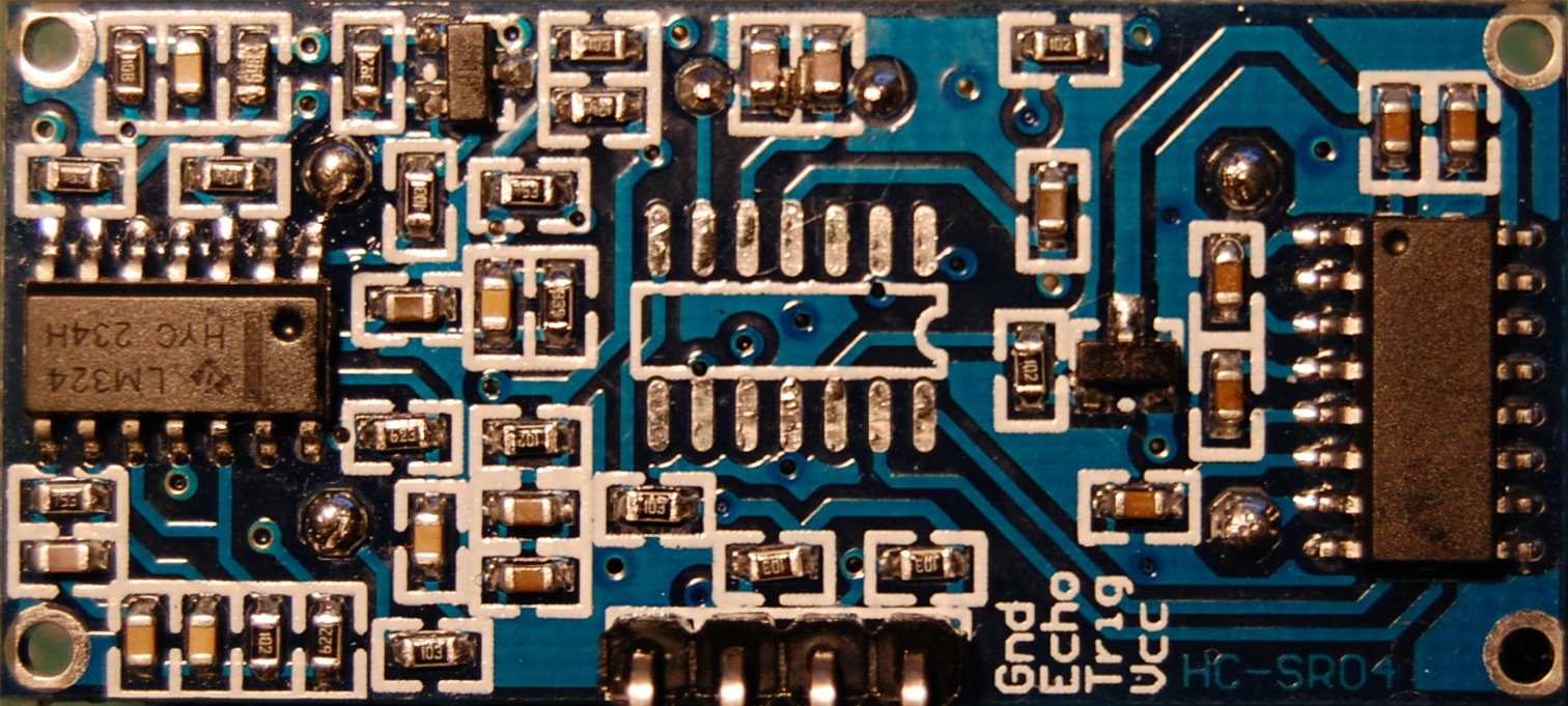
HC-SR04 Front ViewHC-SR04 Back View

They are very cheap especially if you buy a dozen you can get them bellow 2$ shipped. Once they've arrived, to test them, I wrote a quick C test program for an AVR board which displays the distance in cm to an obstacle. The results were pretty accurate for as far as 3-4m distance for hard obstacles. Unfortunately when there are no obstacles in front of this detector or when the obstacles don't have hard surfaces then erroneous results are returned.

I wanted to understand why this was happening so the first step was to reverse the HC-SR04 module schematic.

The circuit has 2 transducers one for emission and one for reception. To transmit the ultrasonic pulses a relatively high voltage is needed. A MAX232 (U3) is cleverly used to produce +/-10V (which are the normal USART voltages) from 5V. The transducer is connected between two outputs so it is in fact powered at 20V. Power is only applied to this circuit through Q2 some time before and during pulse emission because the internal switching charge-pump is noisy. When the circuit switches to receive mode the MAX232 power is cut off. The receive and emit circuits are controlled by an EM78P153S chinese microcontroller running at 27MHz. The receiver side uses LM324 which contains 4 OPAMPs. U2D is just a times 6 amplifier. U2C is a multiple feedback (1st order) pass band filter which is followed by another times 8 amplifier (U2B). The last OPAMP (U2A) is used together with Q1 as a hysteresis comparator. I've simulated the filter in PSpice and it is not centered at 40KHz as it should be but instead it has a 18KHz peak. By changing just two resistors (R13 to 2K2 and R11 to 18K) the filter response is shifted to the pulse frequency and this greatly improves the detection sensitivity.

Bandpass filter centered at 18KHzBandpass filter centered at 40KHz

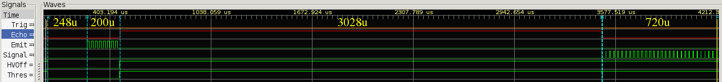
Bellow are some waveforms captured from the circuit. If you want to see them in detail I have saved all traces in VCD format here and you can use the free gtkwave viewer to analyse them.

Regular pulses from a fixed hard surface
Typical waveforms for one echo detection
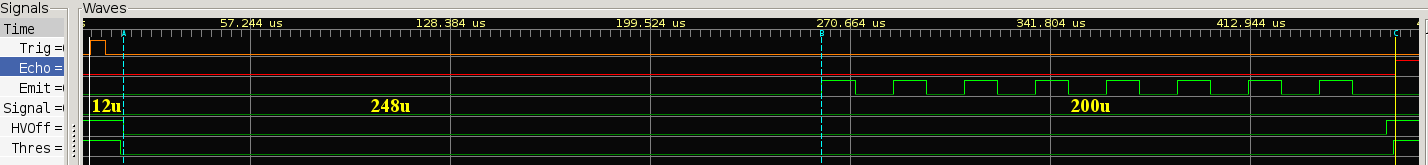
8 pulses at 40KHz are emitted
the echo is longer because of the filter response and multiple reflections
echo when the obstacle has soft surfaces - only some echoes are valid
random echoes are returned when there is no obstacle in front
zoom in on random echoes
retrigger problem when no echo is received
false readings even when triggers are 1s apart (all reflections have died off)

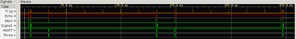
After the trigger input is raised the uP detects it and after some 10us powers on the MAX232. After 248us, time to ramp up the +/-10V of the charge-pump, the 8 pulses 40KHz train is produced and then the power is switched off. During this time the comparator threshold is also kept low to prevent any spurious signals to be detected in the receiver. The circuit then asserts the echo signal and waits for the echo to return. As soon as the first pulse is detected in the receiver the echo signal is deasserted and one can measure the width of the echo pulse to calculate the obstacle distance. There are several problems with this circuit. First the uP uses polling to detect a return pulse. This can be observed because sometimes only the second pulse is detected. There is no attempt to check is that first pulse is part of a 40KHz train of pulses. A noisy environment will probably produce false pulses which will pass trough the analog 40KHz filter (which has a modest 6db/octave attenuation). The circuit biggest problem is the false echo pulses which are returned when there is no obstacle in front. These have a plausible and variable range and cannot be filtered out in software. The processor is OTP so cannot be reprogrammed and there is no easy way to change it and hook another one in its place. The whole circuit is made to minimize the cost to extreme. The 27MHz crystal was unmarked and when I've measured it had almost 1/1000 deviation.

In the end I've decided to change the processor and the board so I can improve this design. The analog part is pretty decent so I will keep all the components except the uP and the crystal.

First I've marked exactly where each component was placed on the original PCB
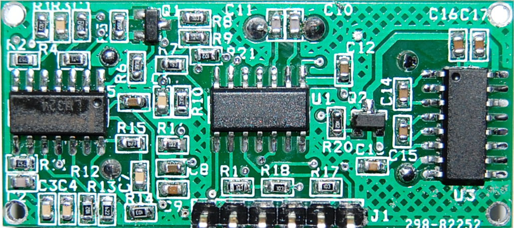
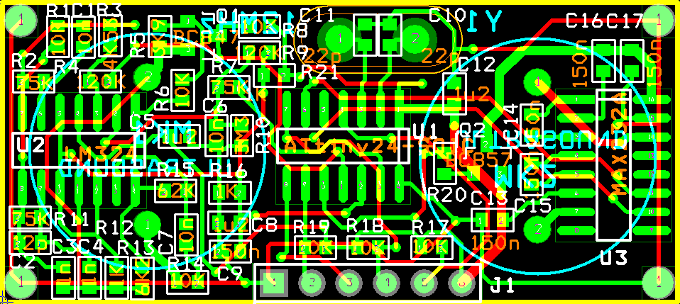
Then I've designed my own PCB keeping the same component locations

I've used the AtTiny24 in a SOIC14 package with a 12MHz crystal. This is the new HC-SR04E Schematic (I've appended an 'E' to the module name), the Bill of Materials and the Gerber files or Gerber panel if you want to use the cheap ITeadStudio PCB manufacture and get 20pcs for a tenner. Soldering one of these new boards takes about 20 minutes. The way I do it is by placing the original and new PCB side by side and desoldering the components from one with a hot air rework station and soldering them back in the same position on the new board. This way I don't have to pay attention to component's values. Also notice that there are now 6 pins instead of the 4 on the old connector.

The advantages of this new schematic are:

I have several plans with these new boards. First I'll just re-implement the original functionality with one Trigger and one Echo output while correcting the false echoes problem. Then I'll make an I2C version where the module triggers itself and computes the distance in 'mm' locally and stores it as a 2 byte value. Another master processor asynchronously reads this data only when needed. One of the available pins will signal a proximity condition when the distance decreases under a certain value. Another iteration will use an open drain pin to sync the emission of several modules to be able to use multiple sensors on the same robot without having to wait for each one to complete a measurement. AVR software to follow when I'll have some more time available.

Since I've written this entry several new versions of the echo locator sensor have been commercialized. Paul has reversed the schematics of one of these and kindly provided a link .

Tags: avr, hc-sr04, ultrasound.

Comments On This Entry

Tom Submitted at 10:06:28 on 16 March 2014
Good work! What is the schematic/PCB package that you use?
Thanks, Tom
Emil Submitted at 13:57:15 on 16 March 2014
OrCAD/Layout v15.7
Mike Submitted at 21:22:17 on 16 March 2014
And you will be selling assembled and tested versions when?
Emil Submitted at 22:05:24 on 16 March 2014
I do not plan to sell anything. The design is open source so if someone wants to pick it up when it's finished they are welcomed.
John Submitted at 01:57:41 on 17 March 2014
Great work. DO you happen to know what the physical difference is between the Tx and Rx transducers?
Emil Submitted at 16:06:16 on 17 March 2014
The transducers have the same physical dimentions, they look the same but they are marked differently. I haven't tried to swap them though. A few years ago I remember designing an echo locator with the same transducer used for both emit and receive but the HV was produced with a transformer and it was as high as 400V. The gain on the receive side was also much higher.
Geebles Submitted at 11:29:49 on 18 March 2014
Have you tested the range/sensitivity to soft objects? I'd be interested to know this for use over grass! Could higher power be used by using so other source to generate a higher voltage? to increase range/clarity of pulses? Looking forward to firmware to come out as i'd be interested in trying this out!
Emil Submitted at 16:05:34 on 18 March 2014
I have not tested the original design sensitivity rigorously. Chairs made of fabric were detected to about 1m. The design I was describing in the comment above was for a 3m diameter quadcopter with one transducer on each arm. On grass the precision was in the cm range and it was working up to 1.5m. I very much doubt that this $2 sensor can sense the grass above 50cm.
Chris Submitted at 17:28:40 on 18 March 2014
I can't help but wonder:
Why is a two-transducer design less expensive to manufacture than a single-transducer circuit?
So many inexpensive sensor modules use two, so there must be a very good reason. I'm just curious to learn.

Another question:
If the new AtTiny software stores all returned pulses, an exciting new possibility opens up. Multiple object detection!
If there at two objects - let's say 1m and 2m - we should receive sixteen pulses in two groups of 8. It could even be useful to know the amplitude of each reflection.
The return value would need to be a more complex data structure, perhaps one byte for number of reflections, two bytes per reflection for distance and one byte per reflection for amplitude.
It may even be possible to estimate the size of a single object.

A great post, you've really got my mind going now!
Emil Submitted at 18:10:46 on 18 March 2014
A two transducer design is less expensive because you don't need to use an analog switch. This switch must block high voltage on the receive side while also having low impedance so that it won't attenuate the received pulses. I remember in my design I've used PIN diodes to protect the receiver side but some of the emission power was dissipated on this input protection circuit.
Domen Submitted at 15:47:18 on 19 March 2014
Hi! Nice project! Thanks for putting it out there, that I can buy this sensor for this cheap :D Just orderd 10 of then from Aliexpres for $12.5. Also, do you have a time frame for the firmware?
Emil Submitted at 21:09:39 on 19 March 2014
The time frame is: whenever I have time. I'm doing this hobby in my spare time and that is a limited resource. If you're in a hurry you can always program it yourself. It's not a hard program to write.
miceuz Submitted at 21:19:43 on 21 March 2014
great stuff, thanks for sharing. Now probably I will desolder piezo elements from the board I have and breadboard it around.
Yogesh tiwade Submitted at 17:58:05 on 6 April 2014
HC-SR04 it is a great kit of ultrasonic tx & rx using 8051..... It a very nice ideal to make a mini project & also used it future for maga project...
RiGonz Submitted at 07:41:01 on 17 April 2014
Hi, Emil! Quite impressed by your work.
Though I'm just an Arduino amateur I've got a question which you seem quite qualified to answer (and as far as I have searched internet and I can judge, probably the best one).
I am trying to use two HC-SR04, so that I can send the ping from one, and read the travelling time on the other. (The reason is that I expect accuracy to be increased, as well as,maybe, the screening range). Then: do you think this can be achieved just from the software side? (I do not even think of desoldering the "drums"!)
Emil Submitted at 11:12:25 on 17 April 2014
With current configuration you can only send the pulses from both at the same time. These will not be in sync because each module has its own clock and the detection of your start impulse is done with pooling. Nevertheless the time shift will not be greater that one impulse period so your error will be minimal. The biggest problem are the false impulses detected when there is no obstacle (at least this happens with the modules I have). This is what I'm trying to improve with my new design. I plan to use 6 of these (all synced together) on a balanced robot and some additional IR sensors.
Jim Remington Submitted at 02:59:54 on 18 April 2014
Nice work! I also had the idea to improve the circuitry, and am glad you were ahead. However, I'm puzzled by the function of U2C, which is appears to be a filter. I used LTSpice to simulate the basic U2C module using the component values you specify on the schematic, and from the AC sweep analysis, it appears that the overall gain peaks at 20 kHz, at -28 dB and drops off from there to -40 dB 12 and 36 kHz. That doesn't make much sense to me, so I wonder if you are certain of the capacitor values associated with the feedback path of U2C. You can email me for the spice file if you like.
Jim Remington Submitted at 03:13:06 on 18 April 2014
I can get the filter to peak at about 40 kHz if C3 is 220 pF,
but the gain is still quite low, at -26 dB.
Emil Submitted at 13:25:15 on 26 April 2014
Hi Jim. Thanks for pointing this out. I've used an RLC meter measure all components and I don't think I've mixed anything up (but it's still possible). When I'll build my next module I'll measure the caps again. If you are right then I'll redesign the filter to be centered at 40KHz. I already have the schematic in OrCAD so I'll use its own Spice simulation.
Jim Remington Submitted at 01:28:58 on 28 April 2014
Hi, Emil:

I played around a bit more using LTSpice (using C3=220 pF), and if I use a .tran transient analysis simulation with a 100 mV AC signal source, I get a gain of 5 (15 dBV) at 40 kHz . The gain drops off as expected from 40 kHz.

However, if I use "small signal" AC analysis, the gain is reported to be -6 dB (in contrast to what I stated before).

I don't understand why the two different analytical approaches should disagree about the gain, but they do agree that the peak response is at 40 kHz. Does your circuit simulation produce similar conflicting results?
Emil Submitted at 23:14:45 on 28 April 2014
You may have saturated your OpAmp with 100mV of signal (you only have 2.5V of "swing" available). You were right, the filter peaks at 18KHz and the voltage gain is 180. I've changed 2 resistors to center the filter at 40KHz.
Jim Remington Submitted at 01:54:19 on 29 April 2014
Emil: The problem I had with LTSpice is that the small signal .ac analysis seems to assume 1 VAC on the input. If you provide a different signal amplitude, the gain is incorrectly calculated. Both approaches now assign a gain of 15 dB to my version of the second op-amp filter (with C3=220 pF).

Cheers, Jim
Nigel Gourlay Submitted at 06:16:45 on 29 April 2014
First, thanks Emil. I'd started my own project along the same lines before I found you're page. I've ordered some boards and in the meantime am building a through-hole version on stripboard so I can get started on the code.

The only alteration from the BOM is C3=220pF to tune the OpAmp to 40kHz?

Also, I see that C1 and R3 are mislabelled on the board for future versions.

Just to check - the package size is 0603 (1608 metric) for all the passives, and all capacitors are ceramic multilayer?
Bernhard Submitted at 09:00:06 on 3 May 2014
Emil: Nice project. I'm currently trying to do the same, but replacing the OTP uP by an attiny2313, then I found your webbpage. I'm wondering if you will provide your source for your attiny solution. I'm interested to adapt your source to my attiny2313 solution.
ikku Submitted at 16:00:43 on 14 May 2014
First of all, good idea!! The original sr04 could use some improvements. But I tried the design in LTspice and when I use an input (sinusoid, 40Khz) of 0.1V the comparator (U2A) starts to do something, but I do not see any hysteresis, and the output is clipped. When I input only 0.01V or lower (sinusoid again) the output signal is a nice sinusoid of only 1.5mVtt, but U2A does not do very much. What am I doing wrong? Also when I see the datasheet of the original EM78P153S it does not have any Analog input capabilities, so how does that work in the original sr04 module? You can shed any light on these issues?
Sverre Holm Submitted at 00:19:40 on 30 May 2014
This is a nice analysis and modification.

If you really want maximal performance, you should compensate for speed of sound variations with temperature also. As an example at 27 C, the program will underestimate range by 5 mm per m of range. This can be found if you search for "Temperature compensation for an Arduino ultrasonic distance sensor" on the LA3ZA Blog.
drtune Submitted at 17:52:30 on 6 June 2014
Thankyou very much for this Emil; an extremely useful resource, I really appreciate your time reversing the schematic, the capture traces, and other info.
zeuss_net Submitted at 19:04:07 on 17 June 2014
thank you Emil. I would like to use this sensor to measure the water level into a water tank but I want to do the measurement with the sensor placed in the surface of the tank but from the outside of the tank .
I have tested the sensor HC-SR04 without your modification but the sensor can not measure the wave transmitted into the tank. I think it is due to the threshold of signal eliminated by the amplifiers and due to the OTP software, it is possible that with your microcontroller I could study and differentiate the echo produced on the surface of the water.
Do you think this sensor have enough power/sensibility to measure the eco produced by the transmitted wave inside the tank?.
Emil Submitted at 01:58:00 on 20 June 2014
All you can do in software is to mask some unwanted reflections. In your case the problem is not the echo from the tank which is probably almost instantaneous but the amount of power that passes on the other side. You will have massive attenuation twice, once for transmit and once for receive. I think you need to place the sensor inside the tank, if your liquid/water is not too salty you can even immerse it and get the reflection of the air/water surface.
zeuss_net Submitted at 12:04:11 on 20 June 2014
I think this sensor is not waterproof and due to the type of transducer (a speaker) I dont know a way to achieve a waterproofness protection, If I varnish the sensor and the rest of the board , the membrane of the speaker will not work correctly.
May be I achieve a solution with another kind of sensor, like the car ultrasonic sensor, but this type of sensor are to expensive, do you know another type of ultrasonic sensor that can I use in contact with water?
Emil Submitted at 15:34:48 on 20 June 2014
The transducers are electostatic, the membrane is a very light metal plate and is not affected by the water. Try it, for a $2 investment you don't risk much.
Nanko Submitted at 15:26:14 on 21 June 2014
hi Emil,

I found the cause and solution for the false echo.
The false echo is caused in empty space by the transmitter unit emitting the trigger pulse.
The trigger pulse causes the air above the receiver unit to vibrate and this is detected by the receiver unit. The solution is to remove the receiver and transmitter unit from the printed circuit board and put them at least 10cm apart. This is what I did and now it works fine, if you don't need to measure very short distances then this solution is ok.
Thanks for your great article and information !
Regards, Nanko
Spaceman Submitted at 13:03:50 on 4 July 2014
Hey Emil! Great work there! My application doesn't use the HC SR-04 per se, but we are trying to build an ultrasonic flow sensor. We've gotten the sensor alone from a dealer which has two terminals just like the "speakers" in the HC. But, there is absolutely no documentation of the same.
Since it is a non-intrusive flow sensor, the ultrasound needs to penetrate the pipe, so I am guessing it is in essence the same circuitry as the HC with some more power, perhaps? It'd be nice if you could share something on the same. Thanks a tonnes!
Raj Submitted at 06:24:11 on 7 July 2014
Emil,

Very nice work, thanks for sharing. As Chris suggested, I'm also interested in detecting multiple objects using this sensor and/or with some additional changes. Any thoughts or ideas?

Best!
Zeph Submitted at 16:07:42 on 7 July 2014
The backside photo appears to have an IC outline for another chip - do you have any idea what that might be or at least what it's function would be, if it had been soldered on?
Zeph Submitted at 16:25:37 on 7 July 2014
Thanks for sharing your research and results.

I'm not sure how the threshold output works. So the uC holds it low while transmitting to avoid immediately triggering. After that, does the uC pull it high, or tristate it to let it float, or use PWM to set a comparator voltage? (probably not the latter).

Have you tested the range change in the real world, based on the adjusted filter? It's strange that they would design "fairly decent" analog circuity and get the filter peak so seriously wrong, so I'm wondering if this was a bad batch or what.

I'm interested in the aspect of checking that a pulse is part of a 40 KHz pulse chain. I am imagining several software approaches to this, tho fitting them into an ATtiny would take some thought. Do you have thoughts on that?

In any case, I'm looking forward to any updates on this project as you have time; I do understand that limitation. Electronics is a sporadic hobby for me as the other aspects of the world need attention too.

Can Submitted at 03:23:06 on 10 July 2014
Dear Emil,

thanks for your sharing. Your work is really very nice and useful. I'm trying to do it. Can you send to me the source code for the micro controller AtTiny24?
I have simulated the band pass filter by using of TINA Software from TI. It seams correctly, but I have make a real PCB and report the result in this site.
Cheer.
Sebastian Submitted at 12:28:10 on 11 July 2014
FYI, there seems to be also another version of the HC-SR04 board around (I ordered a lot from Ali) which follows the same design but has a somewhat different layout, a 4MHz crystal and uses a MAX3232 instead, probably so that it could run from both 3.3V and 5V. It has also a few other changes: Trigger and Echo are swapped on P50/P67, (using your schematic identifiers) R13 and R14 are 6k8, R15 is 47k, it has no C2, R3 is 2k, R4 is 75k, the transistors are marked L6 and M6, and C16 connnects to GND instead of VCC (though the MAX3232 would accept VCC as well according to the datasheet). I did not measure the capacitors yet against your findings.
Scale Submitted at 09:03:24 on 14 July 2014
Dear Emil,

I think that we need only T1IN and T1OUT and GND for the transmitter. I use 5 x 100nF for MAX232 and I get 20V (+10 and -10V) for MAX232. What do you mean?
Cheer.
Raj Submitted at 18:07:22 on 15 July 2014
Thanks for sharing your great work and details on HC-SR04. I'm wondering if you or others have any idea on how to use this sensor to send and receive higher frequency ultrasonic pulses. I'm interested in generating at 2-5 Mhz. Is that possible with the current design with some modification? My goal is to send and receive pulse through glass and I believe 40Khz will not cut it. Any other suggestions are welcome.
Emil Submitted at 16:25:55 on 17 July 2014
This won't cut it at such high frequencies. MAX232 slew-rate is limiting at 500KHz (maybe lower depending on the capacitance load), but the main limiting factor are the transducers. There's no way you can make a mechanical membrane move that fast - the membrane inertia is considerable and the accelerations/decelerations would require huge forces. The only type of sensors which _might_ work are piezoelectric ones.
Paolo Submitted at 14:33:20 on 21 July 2014
Dear Emil, I'm going build some echo locators based on your design.
Can you tell me part number and supply of sensors you used ?
Have a nice day.

Paolo
Emil Submitted at 01:16:40 on 23 July 2014
I don't have the part numbers. I've bought a dozen modules from Aliexpress and the link is in the text above. You won't get a better price if you buy the sensors individually unless you plan to make a production batch. In that case you'd better contact the chinese manufacturers.
Zappo Submitted at 07:52:40 on 10 August 2014
Emil, Nice work. Looks to me like U2A is an inverting gain stage and not a comparator with hysteresis. U2A output gets inverted by Q1 and fed back by R4. Even though R4 connects to the "+" pin, the overall loop gain is negative because of the Q1 inversion. Purpose of Q1 is probably to act as a level shifter since the output high swing of of a 324 may not hit guaranteed logic "1" levels to the micro input.
Emil Submitted at 21:44:27 on 13 August 2014
I generally agree with what you say but the "-" input is not just AC grounded. The uP can change the voltage level on that input and that makes it behave more like a comparator. Also Q1 is not properly biased to work as an amplifier. When U2A output is near 0V the base is grounded and the transistor is blocked.
Scale Submitted at 08:01:57 on 14 August 2014
I have now the PCB and test it. My problem is that I have only on output of comparator around 1V.
1) can you kindly explain me the working of the comparator?
2) how can I modify the circuit in order to get 5V at the output of the comparator?
vasja Submitted at 10:29:13 on 16 September 2014
Emil thanks for sharing your research. But maybe there is a problem. I replaced resistor R13 to 2K2 and R11 to 17K and start testing. At the beginning things looked ok. But then I put sensor module on the table with transducers toward table. Since then the only measurement I get is few cm regardless the actual distance in front of sensor. Looks to me that sensor died. I wonder maybe that is the reason for putting bigger resistors on original board. I saw in comments Jim proposed changing C3 to 220pF for centering filer to 40kHz. Is this approach better? Please help I am lost in analog electronics world.
Emil Submitted at 12:32:07 on 16 September 2014
You cannot destroy the circuit with a high signal amplitude regardless of the components values because in the receiver path you only have 5V and no coils. You can however destroy the sensor itself and this is what has probably happened.
Kaaruvaghi Submitted at 17:11:18 on 16 September 2014
Dear Emil:
Would you happen to know how the voltage source is related to the range measurement? Like if I connect a 5V step-up switching regulator from 2xAA batteries the range gets reduced to less than 100 cms. There seems to be false echoes without a reflecting object, at this max range as well. But measurements within this max range is accurate. Does a lower input voltage reduce the frequency of the 40KHz/8 pulse train?
Emil Submitted at 21:27:42 on 18 September 2014
The frequency is controlled by the crystal so it won't change. Your amplitude will decrease and so will your range. You'll have to check the datasheet for MAX232 and for the chinese uP to see how low can you go. If you use a step-up regulator unless you have very good filtering and decoupling the switching noise will probably get amplified and give you false reflections. A better choice would be to use 3 or ever 4 AA batteries instead.
joao ferreira Submitted at 11:18:05 on 23 October 2014
I'm thinking on using a HC-SR04 to measure not the distance but the velocity of the flow (lets call it the wind) that exists between the HC-SR04 and an obstacle in front of it. Since the distance (L) is a fixed and well known quantity I could do this...
The theory is:
C -> speed of sound = 343 m/s (with correction for temperature...)
t1=L/(C+V) -> time to go and reach the obstacle... assuming V is going in the direction of the obstacle...
t2=L/(C-V) -> time to return...
t=t1+t2 -> quantity measured by the HC-SR04
Some algebra gives:
equation 1 t=2LC/(C^2-V^2)
equation 2 V=sqrt(C^2-2LC/t)
The problem is that I have to be able to discriminate V with at least 0.5 m/s resolution which implies a better temporal resolution which the HC-SR04 cannot give, because it only have 3 mm spatial resolution and that corresponds to a temporal resolution Tr=0.003/343=8.74636E-06 s.
So for example in order to distinguish between V=8 m/s and V=8.5 m/s, using equation 1 and Tr gives L>21.37 meters. A sonic sensor with a spatial resolution of 0.3 mm requires L>2.137 m which is already an acceptable value, but such sensors are too much expensive for my budget.
Using 2 HC-SR04 in front of each other and putting one receiving the signal transmitted by the other and vice-versa (don't know if it is possible...) I would know t1 and t2 and C would cancel in the V equation:
V=L(1/t1-1/t2)/2
but I still have the problem of temporal resolution.
Again, to discriminate V=8 m/s from V=8.5 m/s I still need L>2.16 m which is a very large distance to put 2 sonic sensors in front of each other (only one sensor and a rigid obstacle would be more feasible...)
Emil Submitted at 15:16:02 on 25 October 2014
Without a phase comparator you cannot expect a better resolution than lambda/2 which in our case is 343/40e3/2 or about 4mm. The original HC-SR04 cannot achieve even that because it uses polling to read the input and also it may miss a pulse or two. Even with my revised schematics you'll only be able to get down to some 4mm resolution (and you need to write a proper detection algorithm not just relying on the first pulse). If you then have the time to average over a dozen of readings maybe you'll get bellow 1mm. The theoretical limit is given by the processor resolution (343/12e6 or 30um). You don't need 2 sensors, just one with a fixed hard reflector (a dense wood piece) will do.
joao Submitted at 20:24:51 on 25 October 2014
I also thought on doing several readings. I will do a dozen readings and then take the mode. What I want is to have 4 wind values each second. The problem in using only one sonic sensor is that the velocity of sound (dependent on temperature) does not cancel in the V equation and since these sensors are so cheap i want to use two because doing it i don't have to care about C.
joao Submitted at 20:08:27 on 29 October 2014
I'm trying two sonic sensors in front of each other. one hs-sr04 and one dyp me007 since i don't have 2 hs-sr04 to test. I use the same trig pin (12) in arduino to trigger both sensors and I'm reading the echo pin of the hs-sr04, and the first time to arrive is the signal from the dyp me007 as expected. The second time to arrive is the echo from hs-sr04 itself with the dyp being the obstacle. Now the problem is that although the echo is accurate (1760 us for a 30 cm distance) the signal from the Dyp arrives too soon!! (only 700 us when it should be 1760/2 us). Inspecting the echo pin of the dyp i have the opposite!! The signal coming from the hs-sr04 arrives too late (947 us instead of 1760/2 us). Any clues?
Nejaet Submitted at 10:36:26 on 31 October 2014
Really enjoyed this article post.Really looking forward to read more. Will read on...
gabahr Submitted at 16:59:42 on 3 November 2014
I am also trying to modifie this unit, I wanted to leave a comment on something that was discussed here and know what you think. I talk to one of my good teachers of analog signal, He first suggested to use a better quality op amp as the Lm324 are quite old and they tend to emplify a lot of noise. He thinks something newer like a mcp6024 would really help. (told me something about old op amps having a big offset or something.) The other important thing is that since ultrasound are not linear and the frequency can change depending on the distance, temperature, etc the pass band filter should not necessarily be set at 40khz. The teacher believes 18kHz is quite low for a 4m distance, but it could be because of the poor quality of the transducers and clock so they adapted the pass band in consequence. What results have you got when centering the pass band to 40khz ?
joao Submitted at 22:09:08 on 8 November 2014
is there a way to put the echo pin to high without triigering it (and so without transmitting sound) and then return to low when receive sound from another sensor?
joao Submitted at 22:38:10 on 10 November 2014
I have wind now.... Checked on wind tunnel... The results are fair... Its a pitty that I cannot have more than 4 us temporal resolution which corresponds about 0.8m/s (L=0.3 m).. I have the time to take the mode of 50 measurements of north/south and 50 measurements of south/north each second and then the two modes are used to calculate the wind each second.
joao Submitted at 00:16:32 on 11 November 2014
After all I learned that 4 us is arduino related... It has to do with micros() function that I need to call to know the time that the eco pin in high. My implementation and (by the way) the arduino newping library and pulsein all use micros(). So the temporal resolution is also arduino related. The only way of using both HC-SR04 and arduino and having better than 0.8 m/s velocity resolution is using a larger L (say 1.8 meters which gives 0,13 m/s) but this is not a practical anemometer...So close of building a 30 dollars ultrasonic anemometer... :-(
Graham Submitted at 09:01:44 on 11 November 2014
Vasja says "I replaced resistor R13 to 2K2 and R11 to 17K and start testing" - he then had problems.

I wonder if he or anyone found that the extra gain was as predicted?
Does anyone actually have a fully working "gain enhanced" original board - and what extra range do you get?
Jichang Tan Submitted at 04:44:01 on 23 November 2014
Hello, Emil, how is the AtTiny doing? Have you finished any working prototype to share with us? Thanks. (I am thinking to rewire the circuit to an Arduino and get the signals handled with a more powerful processor.)
Emil Submitted at 21:50:55 on 26 November 2014
Unfortunately I haven't done anything else with this project because I've been busy at work and with my other projects. I wanted these sensors for my 2 wheel balancing robot so once I 'll progress more with the robot mechanics I will pick this up again.
lejaune Submitted at 22:08:56 on 8 January 2015
Hi Joao, Interesting discussion here. I am doing something similar to what you are doing, that is to measure the wind velocity in my backyard, between two posts. I am thinking the simplest way is to move the Tx speaker off the board and place it on an opposite post. Of course, there will be some wires, but I think the signal quality should be better going from Tx to Rx directly without relying on reflection, (and hopefully the wires don't act as transmission media). So the equation will simply be V = L(1/T - 1/T0) where T is the propagation time and T0 is the propagation time when there is no wind, which can be calibrated. I my case, L is roughly 3 meters. So if the time resolution is 4us, then resolution of V is good enough.
I am still waiting for the HC-SR04 board to arrive.
Igor Submitted at 19:16:30 on 16 January 2015
Hello, Emil.
i'm trying to understand (just in theory for now), is it possible to detect an object with diameter 4.5mm and length about 5mm, moving at 170 meters per second speed? I just trying to find a way to measure coordinates of a match airgun bullet without paper target.
Thomas Jimison Submitted at 12:00:23 on 7 February 2015
I am not an engineer so I may not be able to ask the right questions, but I need to send out two bursts of echo-locator pings from synchronized units and then down-scale the return frequency by 10X to make them audible. Is this possible and can it be done underwater?
Ernst Hoffmann Submitted at 22:44:41 on 25 February 2015
Please look at my diagnosis of a wrong working very cheap HC-SR04 from china.
1.) It uses the same IC's as in your description.
2.) The arrangement of the R's and C's is different.
3.) The PCB is different.
Now the wrong behavior.
For small distances it works as wanted. But when the distance is too far, 0 (zero) is returned and no further short distance is measured. Always 0 is returned.
The way out is a short metallic tap to the receiver.
Then short distances can be measured until ...

My suggestion is that there is an endless polling in the
chinese microcontroller (which cannot be reprogrammed).

I will try a curious strategy to work with these faulty sensors: When a 0 is given back I will switch off the power for the HC-SR04 and repower it after a short delay.

What do you think about my suggestion and the alternative.

Ernst Hoffmann Submitted at 20:59:16 on 27 February 2015
There are HC-SR04 with faulty firmware. They contain a "never-ending polling for a never coming echo".
A lot of 10 such sensors was bought via amazon from a chinese supplier.
After my modification even these faulty sensors are working correctly.
My modifications: The Vcc-pin of the sensor is connected to the collector of an additional pnp-Transistor. The emitter of this transistor is connected to the 5V of the arduino board. The base of this transistor is connected via an 1k resistor to an additional controlPin. LOW at the controlPin switches the power on, HIGH switches off. A short HIGH pulse by a digitalWrite( controlPin, HIGH ) directly followed by a digitalWrite( controlPin, LOW ) is enough to reset the ultrasonic sensor. This reset must be done whenever the output of the functions ping() or pulseIn() is 0. So this software initiated hardware reset ends the infinite polling of the firmware in the controller.
Vincent Submitted at 11:50:47 on 21 March 2015
Ernst,

indeed there seems to be a plague of these faulty HC-SR04's. I've got two of them myself from China too. Your workaround works perfectly for me. Thank you and thank Emil for the valuable information in this page!
Lukas Submitted at 18:45:42 on 24 March 2015
Hi,
maybe you could explain this to me:

My chinese HC-SR04 has the exact same fault. All I did is I added an LED to blink everytime the trigger sents signal and somehow this solves the issue with freezing after an echo is lost. LED works like a policeman :D
Try it, and let me know :)
Ernst Hoffmann Submitted at 16:33:13 on 28 March 2015
Hi Lukas, please explain where you connected the LED. Was it an extra pin, or was it parallel to the trigger? Please add the important (not more than 5) lines of the ino file.
carlos Submitted at 19:55:34 on 1 April 2015
excelent job !!!! congratulations !!!
Where can i find the source code for At Tiny ???
frank Submitted at 08:43:45 on 8 April 2015
very nice research emil! the flexibility of programming the micro to adjust the measurement algorithm is just what i (and i think a lot of others!). i have no time to make the boards: would you be willing to sell me a couple of finished boards?
Stan Submitted at 05:20:58 on 10 April 2015
Great stuff.

I am looking for a way to generate (and recieve) ultrasound with a PC or circuit. This one only shoots burst at a certain frequency.

Does anyone know how I can generate ultrasound in say 20khz to 100Khz (or more) using a variable knob like a reciever?
Is there something like that availlable? (not for distance measuring just to emit and view ultrasound)

One of the applications is that I want to measure bats ultrasound frequency but I also want to produce ultrasound and not just in a 1 time burst but a continuous sound

Any help djstandove AT gmail DOT com
Bruce Gennette Submitted at 03:35:12 on 7 May 2015
I'm looking at externally auto-triggering SR04s (from an op amp oscillator), then storing the pulse length returned as a voltage (possibly amplified with another op amp, held on a carefully chosen R-C). Then a microprocessor can sample the auto-averaged voltage at any instant to calculate distance (multiple sr04s, 1 pin each, minimum code and capture time).
But I need to know a bit more about the triggering to make it work :). I don't have access to storage oscilloscopes, so can't derive this info myself. Your waveform traces give me most of the info, but ...

The high voltage circuit turns on just after the Trigger is raised, AND stays on till 500us after it is dropped Lo. How much power does it use per 500us?
Does the HV generator stay on even if Trigger is held high for 1000ms or more?
Is the power usage constant during extended charge-up time? Or is it different for | Initial Charge-up | Hold | Pulse Out | ?
What happens if multiple Trigger raises and lowers occur during the high voltage charge-up time? Does the HV generator also just stay on till 500us after the last lowering?

This will allow me to calculate true power requirements to show the viability and endurance of externally auto-triggered SR04s for battery operation.
Emil Submitted at 18:59:59 on 8 May 2015
You should use a micro to do what you want. I will consume way less power and would be more flexible. Even an 8 pin one will be able to trigger the module and do the averaging.
Alternatively you can build my version of the board and have the on-board micro do all you want.
I don't have access to the original chinese firmware but you can find answers to your questions by looking at the captured waveforms from above.
Jim Submitted at 15:42:04 on 29 May 2015
This is great work. Any chance of posting your Orcad schematic file? I'd like to integrate your upgraded circuit into an existing 1-wire sensor design and keep everything on a single PCB. Also is it possible to get your code for the ATtiny?
Thanks,
Jim
Emil Submitted at 21:18:27 on 29 May 2015
Sorry Jim the OrCAD file contains personal info inside and I won't share it. As for the code I still haven't written a single line yet because I'm busy with other projects.
Anthony Submitted at 18:01:54 on 27 June 2015
Hello. Does anyone have any information about the HC-SR04 being connected to an uC with a long cable as opposed to being close the uC. Basically the sensor is meters away from the uC. Can the echo output driver that much capacitance etc?
Craig Submitted at 13:29:16 on 15 July 2015
Has anybody looked at doing the same on the Ultrasonic US-015 boards, they appear to have an 8 in processor? Possibly directly drop in an Attiny13 processor or the likes directly!?
Craig Submitted at 12:51:05 on 31 July 2015
A colleague into electronics has had a very brief look at the US-015 board I now have. He says the pin outs may match an 8pin PIC processor such as the PIC12F508, this would be a simpler upgrade than the HC-SR04 :)
stephan Submitted at 09:10:12 on 30 September 2015
Dear emil!

Thank for publishing your very interesting experiments . I looked with a mikrophone to the sound emitted of the piezo sender . During the 8 waves the amplitude of the soundsignal is growing . I think what i see is the ( einschwingvorgang ) . After the 8 waves i see much more waves . I think that the piezo continues to swinging because of its mechanikal enegy he got at the beginning .
Did you ever try to look to the emitted 40 khz sound ?
Friendly

Stephan
Maurits Submitted at 11:46:03 on 7 October 2015
Do you also have a revised schematic with the changes to center the filter at 40KHz?
> You were right, the filter peaks at 18KHz and the voltage gain is 180. I've changed 2 resistors to center the filter at 40KHz.

Could you post that schematic as a pdf file?
Emil Submitted at 12:46:03 on 7 October 2015
> Could you post that schematic as an image or pdf file?
I've converted all the schematics to SVG because they are much more portable and you can see them directly in your browser with no external program needed.
SVG is a vectorial format so you can download the .svgz file and open it in the (free) inkscape program and then export it in the format of your choise, including PDF.
Jerry Submitted at 10:21:16 on 3 December 2015
Hey Emil!

I'm currently working on the same project. Any chance you can upload the source code for the ATtiny24 chip?
Emil Submitted at 05:29:33 on 4 December 2015
Sorry Jerry, I haven't written a single line of code yet.
This is not a big task though, it's a simple program using the timer counter.
Ronald Submitted at 21:41:19 on 4 December 2015
Thanks for your post. Stoked by your success I check my SRF02, to see if I could hijack the analog circuitry too. Then I saw the chip was a 16F687, a pic! srf02's are probably reprogrammable...
Antonio Esquivel Submitted at 16:23:29 on 7 December 2015
Which logic analyzer did you use?
Emil Submitted at 17:23:29 on 7 December 2015
I've used a tiny Logic Sniffer with the OLS software
Robert Mueller Submitted at 17:30:29 on 18 December 2015
First, Raj asked about higher frequencies. There are suitable transducers used in medical and industrial applications for imaging and many other applications. Indeed, I believe at ebay you can get tranducers intended for ultrasonic cleaning functioning above 100 kHz and maybe even 200 kHz (not sure) but what seems like a better and cheaper choice are transducers for humidifiers. These are piezo ceramic devices able to drive a "pile" of water perhaps 5 or 10 mm above the rest of the water surface. You can do the Debye-Sears experiemnt with these (make the compression wave in water function as an optical diffraction grating).
But now my question, I have read many of the comments in a great hurry but one thing I miss is mention of "correction" for loss of echo amplitude as the detected target moves father away. Perhaps I have overlooked the text on the subject but with a distance range from a few centimeters to 400 cm and returned signal power then varying inversely with distance to the 4 th power and thus voltage varying inversely with distance squared the effect is not small, on the order of 10,000 in voltage. Do we just let the amps overload at shorter measuring distances on larger objects or is there some trick I am overlooking? This is interesting in setting up an acoustic RADAR (really sonar in air) system where it would be nice if objects of similar size were shown with about correct relative appearance on a PPI display.
Sai_B Submitted at 16:10:17 on 19 December 2015
I want to use the ultrasonic sensor for either transmitter or receiver only....
Can i do that if so what are the measures to be taken?
do we have to disconnect one of the CAN from the sensor? what will be the difference?
Chakri Submitted at 16:22:26 on 19 December 2015
Hi,
How to use HC-SR04 either as a transmitter or receiver separately and to measure received signal strength of ultrasonic signal with HC-SRO4 in arduino?
The problem is that ultrasonic sensor (HCSR04) is printing garbage values even the receiver didn't receive any ping from(echo pin is not connected to arduino) transmitter. Is there any way to process those garbage values?
Thank you.
Robert Mueller Submitted at 17:07:58 on 19 December 2015
To Sai_B
You should be able to do it. You can buy the elements separately and unmounted ar ebay or take them off the board, which makes them a little more expensive but still pretty cheap. I wish I could advise you about two matters, polarity and how so-called "Transmitter " = T types differ´from "Receiver" = R types. When I can find data sheets which treat them as if they were different I can see no real difference. With a third one you might try and experiment keeping the same third one as a transmitter while observing transmitted signals from R ones and T ones. Then run the extra module as receiver and run the others as transmitters and note any substantial difference. If you do it and see any important difference reporting it to all of us would be appreciated.
The matter of polarity is possibly more critical. It is possible to damage a piezo transducer with the wrong DC polarity. Indeed, the ceramic piezo elements (typically fat, washer shaped discs) for ultrasonic cleaning have a mark on one side. Piezo ceramics are polarized during manufacturing and the pre-polarization is lost with time and elevated temperature but that loss is much faster if the wrong DC voltage is applied (wrong polarity). Without explicit data my tendency is to use only AC excitation or at least make the terminal not connected to ground (the can of the transducer) positive. After sending this I plan to search for spec sheets from one manufacturer who supplies models very similar to those discussed here. I will return if (and only if) I find something. Unfortunately, there is no certainty the data will accurately apply! But they would be better than nothing.
If you are in a position to do it and can have a separate power supply for transmitting it is easy to drive a module with a simple transistor saturated switch but cheap low power audio amps could be better. I would recommend keeping the driving voltage no higher than 20 volts peak-to-peak unless you can find explicit data saying higher is safe. The special RS232 transmitter chips are just right for this job and level of drive and might be as low priced as alternatives.
Robert Mueller Submitted at 17:28:48 on 19 December 2015
Back again. The source of data I mentioned is for a device called UST-40T by Monacor. Enter it at Google and you will soon find a data sheet with a bit of information. There is also a UST-40R but its data sheet has values for data having interest for the receiver and these are the same as for the transmitters; however, there are no data for transmitted power or the allowed input drive voltage. You will not learn much but as a transmitter up to 20 volts RMS are allowed (2.8 times what I wrote above if you need it), capacitance is about 2400 pF, receiver sensitivity is 5 mV at 1 Pa and the frequency is 40 kHz +/- 1kHz. Actually the sensitivity is written as 5.0 mV/Pa/1kHz, but I do not understand what the 1 kHz part of the units means! Sorry!
Robert Mueller Submitted at 12:23:33 on 21 December 2015
An alternative with advantages and disadvantages!
While searching for other data I stumbled across an interesting device. I have been trying to improve the common 40 kHz ultrasonic distance modules with horns on both the receiver and transmitter. The goal is a sharper beam and maybe stronger echos meaning some increase in range (with the right settings of the receiver and slower rate of measurements, echos from farther objects can interfere with those of nearer objects if the rate of transmission is too high). Suddenly I discovered a transducer already offering a much sharper beam achieved by moving up the operating frequency rather than increasing the size of the "antennas". This is called SRF235.
There is a price in money (much more expensive) and range, hardly more than a meter depending on the size of an object reflecting the beam. A couple sellers offer these at ebay. The shorter operating range is not a pure loss because transmissions can be more frequent without the above mentioned defect of confusion between near and far targets so for some applications these devices could be a valuable solution to problems.
There is another alternative which sometimes makes more sense, optical sensing with distance determined by triangulation rather than time of flight but the broader beam of an ultrasonic method not only a burden but it can also be a blessing if optical sensing demands much more complex scanning schemes, for collision avoidance, for example.
Ajoy Raman Submitted at 05:15:11 on 22 December 2015
Thank you for this excellent tear down. This has helped me in my latest submission Long-Range-Ultrasonic-Distance-Sensor at instructables.com.
Guy H Submitted at 20:35:39 on 27 December 2015
Few questions to Emil, or anyone else that knows..

In the filter simulation, I didn't see some of the resistors & capacitors, probably because they are part of the comperator logic (R7, R9, R10, C6).
Don't they effect the filter? How would the freq response change if all comperator logic would be simulated?

The value of R10 is 3M3, is that 3.3 Mega ohm?

How does lowering the voltage in Threshold, prevents detection?
Threshold voltage is either 0v or 5v, right?
Emil Submitted at 23:03:02 on 29 December 2015
The output impedance of an OPAMP is close to zero so there is virtualy no load influence on the filter. 3M3 is 3.3Mega indeed. The "Threshold" signal is 0V/5V but it changes the voltage on the negative pin of the comparator form 2.4V to 1V (approx).
LUIZ MELEK Submitted at 17:23:44 on 30 December 2015
Why all ultrasonic boards have 2 usltrasound components ( TX and RX) ? Why is it so difficult to use a component that is a transceiver, with both functions ( RX+TX ) ?

Thanks
Luiz
Emil Submitted at 23:12:55 on 30 December 2015
You can use a single transducer. Many years ago I've built an autonomous flying robot which had just one ultrasonic sensor per arm to measure its distance to the ground (worked for close range only ~1.5m above ground). The emit peak pulses where close to 400V and I had to use a transformer to generate them.

I presume that with this pair solution, each transducer is optimized for a certain impedance. The active element in these sensors is a piezo crystal and between emit and receive you probably have at least 2 orders of magnitude in power. So if you want reasonable receiver voltages well above the noise you put a more sensitive piezo in the receiver.
Raj Submitted at 03:09:51 on 22 January 2016
This is Raj, again. I've a follow-up as I'm still working on my problem. What would it take to program the modified sensor to detect more than one object. I have a need to detect specifically echo from the second object.
Also, is there a place anyone can suggest who can let me upload the schematic and give me a quote on manufacturing X number of samples?

Thanks!
LUIZ MELEK Submitted at 01:02:43 on 5 February 2016
Do you know a version of the HC-SR04 which do not use the BC847 transistors and MAX232 ? Instead a single chip substitutes both BC847 and MAX232. Do you know the part number of this chip ?

I made a board with the schematics you show above, with discrete PTH components and it worked for only 10 centimeters !!! Any idea of the problem ? Do you think the layout is so sensitive that is affecting my version of the board ?

Thanks
Luiz
Jose Luu Submitted at 14:39:50 on 7 February 2016
As of 2016, it seems that there are now (at least) 3 different kinds of HC-SR04, the ebay vendors are starting to also show the back of the PCB. The 3 kinds are:
1)
Traditional like the one Emil has reverse engineered on this page.
2)
Transistors on edge, where the 2 transistor are along the top edge
3)
No transistors, where the microcontroller is turned 180.

I have received someof the type3 recently, they have a sharp filter centered around 41Khz, -20dB at 35Khz and 45Khz.
LUIZ MELEK Submitted at 02:08:57 on 23 February 2016
But what about those maxbotix PIC16F-based ultrasound sensors with only one sensor for both TX and RX (transceiver) ? Have you seen the schematics ? Quite simple. The problem is to find the transceiver exactly the same they use.
Have anyone tried ?
Petr Submitted at 11:56:55 on 25 February 2016
I would like to ask you on the right timing of the signals: Threshold and MidPoint?
sudipta gorai Submitted at 18:00:16 on 26 February 2016
is there any way hcsr04 boards can be used for underwater applications
i have used it in my project but not getting any way that how do i put the devices with hcsr04 board underwater
if i cannot use it is there any replacement for it
Sergey Submitted at 21:41:55 on 29 February 2016
Thank you, Emil!
Simon Kay Submitted at 12:03:47 on 4 March 2016
Emil,
Your efforts are appreciated, and I'll be doing some development work with this. Your schematic capture is particularly useful. It's an odd world when it's cheaper to swap components than buy the BOM, but whatever.
Good luck in your career.
sdk
Nauman Younas Submitted at 19:36:38 on 7 March 2016
Great work....
Mehmet Submitted at 13:57:58 on 10 March 2016
Dear Emil,
How can they achieve reading as minimum 2cm distance?

"the 8 pulses 40KHz train is produced and then the power is switched off. During this time the comparator threshold is also kept low to prevent any spurious signals to be detected in the receiver."

8pulses of 40Khz signal duration is 8*25us=200us ,speed of sound is 340m/s .So to receive all of pulse train ,receiver should be located at 340m/s*0.0002s = 6.8cm far away from transmitter.

Actual distance between transmitter and receiver is about 1cm, so is it enough receive just one pulse to measure distance?
Emil Submitted at 17:59:02 on 10 March 2016
One pulse is not enough. You need to generate a 40KHz (in theory sinusoidal) signal and 8 pulses are just the minimum number of pulses you can get away with. On the receive side you have a filter which also has a group delay adding to the time delay between pulse emission and the receive interrupt signal. Visualizing the received signal on a scope shows a maximum amplitude roughly in the middle of the train pulses so that would be some 300us or 10cm travel distance. Your object needs to be at least half of this distance away (5cm) because it is a reflected path. The distance between the 2 sensors is irrelevant because it barely increases the travel distance and this contribution decreases rapidly with the distance to the object.
javi Submitted at 21:48:16 on 30 March 2016
Thank you for such a comprehensive reversal. I'm stuck with a few HC-SR04 modules from banggood that don't time out, so I've been studying your post for two days now and your schematic is incredibly helpful. I came up with an idea: repurpose the ECHO pin and wire it to the negative pin of the 4th OpAmp (the hysteresis comparator). Then I can get the raw pulses after the 3 previous stages and process them in my own MCU via edge triggered interrupts. I like this idea because I can fix several problems at once: first I can check if it's a train of 8 pulses in a row or just random noise, which the chinese MCU doesn't do and 2) when there's no echo I can bump the chinese MCU by pulling the (-) pin comparator high. What do you think??
javi Submitted at 00:32:28 on 31 March 2016
... correction: I meant the (+) positive pin of the comparator. I'm also thinking of sampling that pin analogically and calculating the RMS envelope. Then finding the peaks would give us where the obstacles are located. When there are multiple object with partial or no occlusion, I would even expect multiple local maximums and thus we could "see" more than one object. I have to experiment with this.

Also worth mentioning: looking at the comparator's threshold on the scope, it looks like they are using the charge ramp-up of C6 to compensate the echo losing power with distance. Very clever.
Johng807 Submitted at 22:16:34 on 7 April 2016
I really like your writing style, excellent info, thank you for putting up eekdafgebbce
Johnc661 Submitted at 22:16:36 on 7 April 2016
Real nice design and great articles, nothing else we want ecdcaddkgdea
Kalesha Submitted at 12:42:25 on 10 April 2016
What is the purpose of connecting two GPIO pins to T1IN and T2IN in MAX232..can we use a single GPIO Pin to connect both T2IN and T1IN?
Anthony Robertson Submitted at 17:46:59 on 10 April 2016
Extremely impressive work Emil.. Please let me know when redesign is completed and available
Dave Evans Submitted at 22:06:31 on 30 April 2016
Has anyone found a schematic for the HC-SR04 that has no transistors?
Marcus Buchner Submitted at 12:57:18 on 5 May 2016
When I did a Project with this Sensor, I got unstable readings. When pointing it against a flat ceiling, the calculated Distance was jumping around by 3 cm between Measurements. I used Interrupts on an 16 Bit timer, so no chance there of missing a Signal. Anyone got an Idea to why it happened?
You do show nice improvements to this cheap little sensor.
Bill Submitted at 02:36:46 on 24 May 2016
@Marcus Buchner
You didn't say which sensor you talk about. The SC-SR04 or the 'Emil-sensor' if I may be so bold to differentiate this way. Also, didn't say the distance measured. Also didn't say the target material.

If you talk about the SC-SR04, I have the following readings using Arduino Mega2560, NewPing library.
Hard target (concrete) parallel to sensor: max distance ~4 meters, 3 cm jitter
Hard target (laminated desktop) at 16 cm distance. Rock solid reading, no jitter. Jitter happens around 16.5 cm jumping between 16-17 cm. Quite normal. The jitter must be a few mm; we are reading cms.
Soft target (Human body, dressed, standing and sensor is aiming at the chest)max distance ~1.5 meters 3-5 cm jitter.
Very soft target (tissue) at 16 cm distance. Sometimes correct reading. Jitter is between no reading and 25 cm.

Quite understandable. Soft materials absorb the sound.

Sensor above head 2.4 meters high from a concrete floor and a ~180 cm tall person is standing under it- the measurement goes crazy; jumping between 240 cm and ~60 cm. Which is understandable given the small small, irregular soft area of the head, then the shoulders further away.

In other words, the surface type and area can/does influence the measurement.

Also, 3 cm at 100 cm is a 3% error. At 200 cm it's only 1.5%. For the $2 I don't expect a precision module.

Don't know anything about the 'Emil-sensor'.

Also, thank you to Emil for this page!

Cheers
Bill
FSL Submitted at 16:38:39 on 31 May 2016
I am working on a project to calculate frequency difference on outgoing and incoming pulse. I am looking for help in creating schematic for this circuit. Has someone worked on such a project? Any help would be highly appreciated.
Stephan Submitted at 19:16:00 on 4 June 2016
Dear emil!
You write that " the echo is longer because of the filter response and multiple reflections " . Isnt it possible that the piezo beginns swinging in resonance so that it takes a lot of energy and so it swings further also when then 8 periods are finished ? In the osci-picture of a microphone I believe to see that .
Paul Submitted at 07:34:02 on 14 June 2016
I would like to know one that can we use the same circuit for 1MHZ transducer by making some changes?

If yes please suggest me where I need to do that?

My purpose is to measure the velocity of flow of water through the pipe in my building...
Johnny Petersen Submitted at 11:42:35 on 16 July 2016
I intend to use the circuit as a fuel tank level meter in my boat.
Do u have any experience of measuring the distance to a liquid, and do you know if transducers can withstand to be momentarily splashed with Diesel? (I intend to cut holes for the two transducer in the top of the tank and measure the distance from the top of the tank to the diesel level)
The tank is of steel measuring (h)20*(l)40*(w)25 cm in height. When knowing the distance to the top it is just a simple calculation to find how much diesel remains
Mehdi shahzadian Submitted at 17:24:37 on 2 August 2016
Hi emil
I was curious about this circuit so
I analysed it with proteus and the peak was exactly in 40Khz (44db) with the original values with no distortion .
Emil Submitted at 04:15:05 on 4 August 2016
You are either doing something wrong or the Proteus simulator is no good (maybe that's what the chinese designers used ;-).

You can calculate it by hand: U2C is an "Infinite Gain Multiple Feedback Active Filter" an if you substitute the values in the resonant frequency formula you get 1/(2*3.14*sqrt( 0.86 * 75 * .001 * .001 ) ) which is 19.8KHz. R12 and R13 are parallel and C2 can be ignored.
Mehdi shahzadian Submitted at 04:33:47 on 4 August 2016
Sorry, My bad, that was with your values :)
Suman Kumar Jha Submitted at 14:12:11 on 8 August 2016
From last 3 month i am working on one project for that i have to use waterproof ultrasonic sensor, so i buyed from ebay (SR04T). It is working gud but it can't measure obstacle in the range less than 20 cm, which is a great problem for me. I want obstacle detection in between 5 to 150 cm. Please help me.
Moreover after doing research i found that this problem is because of switching delay from rx to tx and again tx to rx.

Now i am planing to make my own design and pcb, i got many help from your post.

One problem i am facing, i am trying to replace SR04 transducers rx and tx separate one with waterproof SR04T transducer(rx tx in one). I am using this two waterproof transducers on SR04 pcb. But it is not working.
Emil Submitted at 20:34:13 on 8 August 2016
Suman,

I'm no expert in ultrasonic transducers. I've just reversed an existing one for my own project which doesn't involve submersible measurements.
Suman Submitted at 12:03:47 on 9 August 2016
Thank You emil for giving response.
Alex Submitted at 12:44:08 on 10 August 2016
Very useful, indeed. I do apologies if I missed that but
finally which accuracy we may have at HC-SR04?
Could we measure longer but with less than 1 cm step?

Somewhere I seen 0.3cm but with using temp sensors.

Alex

Emil Submitted at 19:53:27 on 10 August 2016
It depends a lot to the shape and the hardness of the object you want to measure. Secondary reflections from other objects may influence your measurement. From my experience you can get down to 1 cm accuracy for not too far and hard objects, if you average over a couple of measurements.

At 40KHz your wavelength is 8.5mm and you can't get bellow that because of wave diffraction.
Valen Submitted at 17:29:56 on 12 August 2016
Sparkfun just added a HC-SR04-like module to their store. I say "-like" as it seems to lack the MAX232 chip found on most modules. Could be interesting to compare the performance of both. Whether the MAX232 chip is adding noise to the amplifiers rather than boosting the transmitted wave.
Suman Submitted at 10:45:56 on 16 August 2016
Hey Emil, can you help me i am trying to use ATtiny24 microcontroller, but getting problem in programming. Can you clear me whats a need of midpoint and threshold, its a DAC output or ADC reading.
Can you forward me your program.
It will be really helpful for me.
Emil Submitted at 22:12:04 on 16 August 2016
Neither ADC or DAC. It is just a comparator (1 bit ADC if you want). The threshold is changed outside the reception window to reduce the number of spurious pulses.

I cannot help you with your program. You'll have to develop your own.
Andrew Submitted at 03:25:13 on 19 August 2016
Thanks for putting this out here, had a cap break off on one of mine and wanted to replace it. Just needed to know the value.
Kadir Submitted at 18:13:09 on 24 August 2016
Hey Emil, nice work and detailed explanation.

I have a simpler question. As is, is it possible to get cross readings from two SR04's?. SR04A reads B's echo and vice-versa? Thanks.
Emil Submitted at 21:57:08 on 2 September 2016
It is if you synchronize them - that means to use my schematics and write the appropriate code.

With the original SR04 you cannot do this because they fire the "chirp" at intervals which are not correlated with each other.
Cezar Submitted at 15:13:41 on 11 September 2016
One question regarding the max232 output voltage -
if T1OUT swings between -10V to +10V while T2OUT sends opposite phase pulses of +10V to -10V, then when any of these outputs is taken as reference, the other pin voltage is +/-20V.

That shouldn't be considered a 40Vpp output ?

Thanks

Emil Submitted at 21:59:41 on 21 September 2016
Vpp means "point to point" - when one voltage is 10V above ground the other is 10V bellow ground so the absolute difference between them is 20V not 40V.
jmay Submitted at 17:40:02 on 22 September 2016
Regarding the question from August about pinging back and forth between two modules: this would be a hugely useful feature, so much so that I'd suggest you consider actually manufacturing your version of the module for sale.

Right now, a robot in a room doesn't know where it is. There's no easy, cheap way to solve this problem. If, however, you put one module one your robot, and two others in corners of the room, and IF they can talk to each other rather than pinging off the walls, you can get a super-accurate short-range position for your robot.

Given module A and B: A pings, but ignores the immediate ping back. Module B hears the ping from A, and then WAITS say two seconds. Module B then responds with a ping back, which module A hears. The round trip time minus two seconds tells A the distance between A and B

If the "pings" could have different signatures, say somewhat different frequencies (the eight pulses I mean), then it would make working with three modules easier, allowing triangulation. You could do it anyway, probably, just harder to coordinate.

This would, in my opinion, be a very big deal for makers of small mobile bots. I'm not in a position to make these modules from your plans, but I'd buy them.
Emil Submitted at 15:07:05 on 23 September 2016
Unfortunately I don't have the time for manufacturing anything. I have a full time day job and what I share here are just my pass time home projects.

I have also modified these sensors for my two wheel balancing robot. In my case I have six modules around my robot and all emit a pulse at the same time and then listen for the echo. I can do this because I can run a wire between all of them. In your case you'll need a radio link between your robot and the sensors in the corners to synchronize them. Also using different frequencies is not feasible with the current comparator based receiver.

I should mention that in my balancing bot the ultrasound sensors are used for navigation only, for short distances and obstacle avoidance I also have 5x SHARP 2Y0A21 optical sensors.

Guilherme Submitted at 19:48:00 on 23 September 2016
I did the reverse engineering in this sensor like you. After understand all topics from the sensor like: sending signal, receiving signal, 1st opamp - Amplify 6 times, 2nd opamp 40Khz filter, 3rd Amplify 8 times and finally 4th opamp the threshold comparator.

The next step to finish this project is write a code.
Tom Roberts Submitted at 05:44:29 on 17 December 2016
I am using the SR04 with a Raspberry Pi, and about 1% of the time I get an anomalously low value, which can range almost all the way down to 0. I suspect this is timing errors due to Linux, but direct timing tests indicate that is unlikely. The Pi is idle except for this, but of course WiFi traffic can happen anytime. Has anybody else seen this? Any ideas?

Also, the values for a fixed distance from a concrete wall come mostly at 3 values separated by 4.5 mm, which "just happens" to correspond to the 40 kHz pulse interval. So it looks like this is the SR04 missing one or two initial pulses. The standard deviation from that wall is 6 mm.

As for separating T and R, I desoldered the transmitter from the board and connected it via 15 feet of twisted pair. It works just fine as long as the T is pointed at the R.
Manuel Submitted at 14:55:39 on 22 January 2017
Hei, nice Work.
Can you explain how you programmed the ATtiny and the SPI device?
Emil Submitted at 05:56:31 on 24 January 2017
The ATtiny has no bootloader so it's programed via the SPI interface using any cheap AVR programmer you can find on ebay or Aliexpress. This document explains the in system programming.
Paul Submitted at 11:35:16 on 1 February 2017
Thanks for your work which helped as starting point in reverse engineeering later revisions of these units as I have several batches I am investigating for a school as some work weel and some don't. Some have faults.

I have updated schematic available contact me to get links.

If you are going to build your own board I would suggest a couple of things

Modify circuit so the RX transducer is NOT tied to GND but to mid-rail (nearest point pin 12 of op-amp), then you can remove C7 in your version of the schematic (C1 on latest versions I have seen).

Additionally use any drop in replacement op-amp with Rail to Rail I/O (RRIO Offset voltage less than 10 uV (many exist) LM324 is around 2mV GainBandwidth of 2MHz or higher

Many of the signals get clipped from my scoping introducing all sorts of harmonics so less efficient operation.

With Rail to Rail I/O and your own micro you can make a proper Schmitt Trigger for final stage with better controlled threshold control for squelching receiver before start of echo, without the time constant issues of C8.
Emil Submitted at 06:06:27 on 8 February 2017
Very pertinent comments, Paul. Thanks for your input.
LNG Submitted at 20:36:20 on 14 February 2017
Very nice work!

Can I ask what transducers that I need to buy for the transmitter and receiver if using your circuit and board? What are their part numbers? Thanks,

LNG
Ian Submitted at 22:33:56 on 19 February 2017
I have a later version of this board, marked as a HC-SR04+ this has many changes, specifically I am interested in enabling and disabling the transmit (but still monitor for a received pulse) - I was planning to drive base of Q2 low to disable this - BUT Q2 HAS BEEN REMOVED!!

it also looks like all the MAX232 charge pump capacitors have been removed - and now the IC driving the transmitter (U3) pins 4 and 6 are being driven by by the uController (U2) pin 10, and pulled to vcc by a 10K.

There appears to be no connection to U3 pin6 (VCC?)

Has anyone experienced this version of the board - and reverse engineered a schematic - if so - please can you post a link (Paul you mentioned a later revision) - Thanks
boris sprat Submitted at 21:57:24 on 21 February 2017
@ Paul ditto of Ian's comment, can you post your links to this thread by any chance?

Boris.
PS must look up "squelching receiver".
alaric Submitted at 05:32:52 on 10 March 2017
Part of your circuit board design is now a Brian Jonestown Massacre album!
Emil Submitted at 16:45:44 on 10 March 2017
That's so funny and unexpected! I haven't heard of this band before but some of my mates have. I had a good laugh ...
Sid Submitted at 12:13:39 on 30 March 2017
I am thinking of making velocity detector using HCSR04 by applying doppler effect on the received frequency. Can you give any insight on how to use HCSR04 for this purpose.
Emil Submitted at 21:02:11 on 31 March 2017
This is not feasible in my opinion. For a velocity of 5m/s you need to measure a frequency offset of 1.5%. This is only achievable if you process the analog signal with complex circuitry (mixers and filters) and if the carrier is constantly emitted.

The other problem is the very limited range of ultrasonic sensors.There are professional ultrasound radar units which can measure the speed of a tennis ball and they barely cover the size of a tennis field.

You would be much better served by a cheap microwave radar like the HB100.
Godefroi Submitted at 14:41:49 on 9 May 2017
I would like to know what is the sound pressure delivered by the sensor HCSR04 ?
Emil Submitted at 20:47:53 on 24 May 2017
I have no idea. This information, if available, could be only found in the transducer datasheet and it will be only given for a particular distance and orientation.
Artem Ismagilov Submitted at 09:36:21 on 4 August 2017
Nice article! I want to know what is the controller threshold pin is used for.
Thank you!
Emil Submitted at 17:48:33 on 7 August 2017
The threshold pin is used to inhibit the receiver (by increasing the comparator threshold voltage) during the emitting pulses. You can create a time window when your reflected pulses are received and ignore spurious pulses outside this window.
Rohit Submitted at 18:49:17 on 9 August 2017
If there are two objects - one at 5cms and other at 100 cms,
After sending the trigger, if we put a blanking circuit to keep the threshold high for few milliseconds (to inhibit the echo from 5cm object) , will this reduce the pulse width of the echo thereby not allowing the 5cm object to be detected, and detect the object at 100cm - or will it show 95 cms distance for the object kept at 100cms?
Emil Submitted at 14:23:08 on 10 August 2017
If you keep the threshold high then you mask the nearby objects. You can also mask the far away objects or the multiple reflections. The distance is calculated in software and is not influenced by the masking period.
Cosmin Cadar Submitted at 10:19:10 on 5 December 2017
Hello. I need to emit a 40 khz wave to test a flow sensor. I thaught i can modify the arduino module to produce a continuous 40khz wave. Can you help, please?
Emil Submitted at 02:48:49 on 6 December 2017
I'm sorry, I can only help with clarifications about this article, not writing code for you. You can make a continuous wave in AtTiny24 firmware but the wave energy will diminish to the amount of what the MAX232 charge-pump can provide.
Emiel Kosse Submitted at 09:36:28 on 13 December 2017
I quick look-up showed me your page. Did you know that your layout design is used on an album cover of Brian Jonestown Massacre - Don't get lost.
Emil Submitted at 12:46:36 on 15 December 2017
Yes, It's mentioned in the comments above. Not my kind of music though.
Jenifer Ricalde Submitted at 05:16:28 on 3 February 2018
I am conducting a study regarding ultrasonic sensors and I'm using a separate transmitter and receiver transducer. I'm wondering if you can suggest an amplifier circuit between the microcontroller and transmitter so that it will transmit waves of higher power.
Emil Submitted at 05:31:49 on 3 February 2018
The transducer behaves like a capacitor. The only way to increase the transmit power would be to raise the driving voltage. I've used in the past some ultrasonic transducers which would withstand pulses of 400V but nobody knows the characteristics of these chinese ones.

You can either experiment raising the voltage until they fail, or you can use others with proper datasheets.

Another cheaper option is to use several transducers in parallel all driven by the same microprocessor. If the capacity increases to much for one single MAX232 you can put those in parallel as well.
Jose Manuel Gayoso Submitted at 20:12:28 on 28 February 2018
In my opinion, when threshold signal is high, it enabled C6 to start charging throw R9.
It's a common practice in echo systems to ramp the gain (sensitivity in this case), to make the system capable to detect a weaker signal when target is farther.
Comparator U2A compares the amplified signal (having DC level VCC/2) with the C6 voltaje (a charging ?ramp?).
When the target is far, C6 voltage reach VCC/2 and U2A comparer start giving false values due to the noise of the amplified signal.
I think that putting a diode between R9 and C6, limiting the charging voltage of C6 to (Vcc/2 - Vdiode) can solve the false readings problem.
m.shen Submitted at 19:29:53 on 2 March 2018
a fine analysis of the HC SR04 !

Question
(1) Could transmit power be increased x4 by using emitter followers driving (say) 4 transmit transducers ?.

The receiver would be as before.
============================
(2) Has your 2014 discovery (!!!) of 18khz BP instead of 40khz BP, is that an ERROR that has been corrected today: Mar 02 2018 ?

thank you
m.shen
Emil Submitted at 02:54:56 on 6 March 2018
1) Yes you can increase the transmit power with more transducers. Emitter followers won't help because the load is mainly capacitive. The limiting factor is the charge pump of the MAX232. You can add transducers in parallel and watch the output signal on a scope until the voltage starts dipping.
A better option is to use my version and sync the sensors so each has its own driving circuit but they all emit at the same time.

2) There are so many versions of these sensors out there that you can't say which has the filter frequency corrected until you measure the passives.
David Peruso Submitted at 11:51:26 on 6 March 2018
Have you seen the new HC-SR04? It has only two chips an ASIC chip for the drive signal and receive signal timing and the LM324 opamp. I'm currently reverse engineering the circuit to see what other differences there are.
Frederick W Submitted at 04:19:33 on 25 March 2018
Emil, this is a great project but being able to emulate it seems nearly impossible without the same original hc-sr04 you used these will cost $15-20 each to assemble on my own here in the US. Do you know of a seller on Amazon or aliexpress still selling the version you purchased?
Emil Submitted at 15:48:38 on 25 March 2018
Hi Frederick,
There are many versions that have been produced since I've documented this echo locator and I haven't kept track of all the changes made since.
To build your own you only need the transducers and you can get those from any sub-$ module. You can get the rest of the components (attiny, ICs and passives) from aliexpress.
Jenifer Ricalde Submitted at 16:12:24 on 25 March 2018
I'm currently working on making a receiver circuit for my ultrasonic sensor. I'm wondering what opamps I should use and what gain should I set to be able to come up with accurate results. Any idea? Thank you in advance for your answer, Emil.
Emil Submitted at 15:21:56 on 28 March 2018
Any opamps are good including J-FET opamps like the TL07x series which have high impedance (like the sensor). The gain depends on the required sensitivity. Unfortunately the more you increase the gain the more you'll get secondary reflections in your signal. For example if you choose a gain of 100 then you'll need an opamp with the unity bandwidth 100x40Khz (4MHz)
adam Submitted at 07:29:29 on 2 May 2018
I have two questions:
(1) for the first waveform captured from the circuit: "Regular pulses from a fixed hard surface" or later received echoes, I just could not get those square waveforms from the circuit. I use Scope to check many positions, such as the two ends of the receiver, all I got are damping signals with a long tail. Actually, this should be the right from physics as oscillation on the receiver should be a long damping process. please let me know how do you get those square signals.
(2) I plan to use a dozen of Hc sr04 installed on a line, to detect the position changing of the object(moving slowly around 0~1 m/s). Any suggestions you could have?
Jojo Submitted at 07:25:47 on 29 May 2018
Thank you for sharing your knowledge. I just don´t get how you proved the mistakes due to the polling procedure of the microprocessor. What traces have you measured to verify your statement?
Jan Submitted at 19:28:20 on 5 July 2018
First I want to thank you, Emil, for this great research.

@adam´s (1): I also watched the voltages on the transceiver and receiver pins. The transceiver shows the 8 squares first, followed by ~30 sinusoidal periods, of which the first are still growing in ampitude. Obviously the 8 only start the oscillation, then the MAX232 is separated from power and the free swinging piezo crystal induces the remaining 30 oscillations. The reciever also shows harmonic (sinus) oscillations growing to about 100 mV within the first 10 or 15 periods and after that decreasing in amplitude slowly. The analog circuitry amplifies them so that they are clipped, resulting in smaller and broader squares.
Jan Submitted at 19:35:04 on 5 July 2018
One more observation:

I wondered why some of my HC-SR04 sometimes wouldn't find an echo, even when they are pointing to a hard surface closer than 100 cms. With the help of a digital scope I found out, that the MAX232 is sometimes powered for the 250 or so microseconds, but then stopped again without the 8 squares showing up!
Jan Submitted at 20:49:35 on 6 July 2018
Today I tested another HC-SR04. Quite different behaviour. Only the 8 expected squares, no free swinging afterwards.
Vedant Jaju Submitted at 05:18:46 on 10 July 2018
How many minimum sound pulses out of 8 are required to sense that sound has recieved at reciever??
Jan Submitted at 10:53:12 on 13 July 2018
You need about 8 pulses to get the transceiver going strong enough for a larger distance. The incoming sound is a growing sine-wave. Once a threshold is reached, the receiver will sense that sound has been received. This happens quite early when the reflecting obstacle is close. I haven´t observed an obstacle further away than half a meter on the scope.
Giuseppe Submitted at 07:40:32 on 7 August 2018
hello, to get a better performing sensor I recommend using only one 40KHz TX / RX sensor protected by water and with SPI / I2Cbus interface and / or canbus.
Larry Smith Submitted at 05:27:45 on 14 August 2018
Thank you very much for all of your fine work on this project. It has helped me very much with my understanding of the unit and thus moving forward with my own project.
Kyle Willis Submitted at 01:06:01 on 27 August 2018
How are you getting 2.4 volts for the threshold? The math and simulation show the voltage being 3.9 volts when threshold is high.
Emil Submitted at 02:27:41 on 27 August 2018
R16,R21 form a midpoint divider so 2.5V, The currents flowing into opamps inputs are virtually 0 so R15 current is also 0 so U2D output is at the same 2.5V potential so R12,R13 currents are also 0 and don't count. R9 is 120K compared with 0.5K R16||R21 so this 2.5V midpoint barely moves.

So the threshold value is given only by R9,R7 and the midpoint voltage and is for P61 at 0V -> 0.96V and for P61 at 5V -> 4.04V

So the 3.9V seems reasonable; I might have miscalculated the high voltage in my previous reply.
Izi Submitted at 17:16:15 on 27 September 2018
Hello there, your work is amazing and is deeply appreciated. I've been trying to simulate the filter but somehow I keep getting no response in my results. It's not peaking at 40kHz or even rising for that matter. Can you share with me the parameters of your simulation?
Mimansa Submitted at 05:15:11 on 6 October 2018
Is the micro-controller used on ultrasonic module HC-SR04 EM78P153S or EM78P153A? And what is difference between them?
Emil Submitted at 16:57:20 on 6 October 2018
It's unmarked and I haven't bothered decapsulating one to look for die marks.
kyon Submitted at 07:43:26 on 1 November 2018
I was so confused by how HC-SR04 really works until I saw your waveforms pictures. It seems that so many ppl are just happy with getting few lines of sample codes running w/o caring the principles behind. I was really upset that I couldn't find anyone could explain it w/o copying & pasting sentences from Arduino & SR04 website, until I read about your project & article.

I still have one question though. Since there is a 200us delay between the 8 pulses and echo receiver rising edge, does it mean that there is always:
343m/s*200us=68.6mm offset of the sound wave traveling range
so the measured distance is always 34.3mm short?
Gimo Submitted at 14:40:53 on 4 December 2018
I followed these materials and got the HC-SR04 board to work with Arduino Due. I have one problem - the range drops badly and I can only measure distances below 12cm. I suspect that is because my Due gives 3.3V on the threshold pin.
ritesht Submitted at 06:35:11 on 6 January 2019
Hello All,

I stumbled upon this post with the intention of finding a waterproof sensor with small blind/minimum distance but I could not find it.

Then to my surprise there is a new sensor

www.ebay.com/itm/253978673298

It has 2 transducers instead of 1 so it has smaller minimum detection distance as compared to JSN SR04T.

Also its main board is not exposed like the JSN SR04T since it looks properly sealed and is therefore fully waterproof.
Naeem Submitted at 04:55:55 on 11 February 2019
Nice work
subirol Submitted at 11:16:32 on 13 June 2019
I am wondering if the HC-SR04 work if the receiver and emitter transducers are replaced with a water resistant or water proof transducer?
Emil Submitted at 21:46:34 on 17 June 2019
I can't answer you this. It depends of the specs of your transducers. You can try replacing them because the transmit voltage is low and it won't destroy your water proof transducers. Also if the peak frequency response is something else than 40KHz your receive signal will diminish.
adithyan Submitted at 15:20:34 on 26 June 2019
I am building obstruction locator using HC-SRO4. I have a small problem.
I use a timer to trigger every 3 seconds.(1.5secson/1.4 seconds off) powering the timer with 5V. this is continuous triggering. The triggering voltage at high is 4.5V and dips to zero when off. The echo receiver gives output of 3.5 to 4V even if there is no obstruction. I examined the response of receiver by sending zero volt on trigger to ensure there is no false trigger. in such condition the receiver did give 0v output. I am unable to understand how the receiver gives high output even if there is no obstruction and why should echo pin give a logic high output. Did you come across any such problem and if so how it was solved.
adithyan Submitted at 10:20:41 on 30 June 2019
I am developing obstruction sensor using HC-SRO4. Instead of a micro, I use a timer to trigger it every 25 seconds. the pulse pattern is 15 microseconds on 10 microseconds off. The TX pin shows 4.5V when using 5V. My problem is the RX pin responds immediately giving a trigger of 3.5V even if there is no obstruction encountered. I also tried the timing as 1 sec on 0.5 sec off. Even then the problem persists. Someone suggested to put a tube on TX or RX of 8' length. But that also failed. CAn it be a radiation of 40 Khz within the board itself to cause this problem. If any of our fraternity had similar problem and solved it successfully, can I know it by email since i am in urgency.
best regards
shree
adithyan38@gmail.com
india
EMs Raj Submitted at 06:19:58 on 23 August 2019
Dear Emil, I want measure sound velocity in under water, so I want modify the frequency from 40Khz to 1Mhz but hc-sr04 can works with 40Khz, is it possible to generate 1Mhz frequency from EM78P153S microcontroller? I want change filter circuit for 1Mhz in receiver and replace 1Mhz waterproof sensors. I want you help how to change hc-sr04 TX frequency 40Khz from 1Mhz. Or 1Mhz ultrasonic sensor like hc-sr04 available?
Thankyou..
EMS Raj Submitted at 06:31:42 on 23 August 2019
Dear Emil, is it possible to generate 1Mhz frequency from ATtiny- 24 ?
Daming Submitted at 07:22:48 on 21 October 2019
I just saw your article and learned a lot from your great analysis 5 years ago.
Here's another question.
As I can see in various HC-SR04 versions, there is a small signal received by the receiver right after transmitting the signal. If the signal is amplified big enough to exceed the threshold of the 4th comparator, the module would make a 7-8cm measurement output.
After replacing 18KHz BP with 40KHz BP, the total gain would increase 5 times for 40KHz signal, would it make the error measurement to occur more easily?
I tried to change the gain of the 3rd amplifier to mitigate this problem, but I'm not sure if it's the right way.
Art Submitted at 14:19:54 on 28 October 2020
Hi, I was wondering how far you were able to extend the range
Frank Submitted at 05:20:07 on 1 November 2020
I have been reading all the comments on this post for almost 1h and I have learned a lot. As a result of reading it, 2 questions have arisen:

1- What is the minimum theoretical amount of distance that the sensor modified by you can measure? I would like to know if the sensor is capable of measuring distances with an accuracy in the order of millimeters or, if possible, below that order.

2- In response to @Mimansa about the uC used by the original sensor (without your modifications) you said that: "It's unmarked and I haven't bothered decapsulating one to look for die marks". Could you explain the process? Or share a link to learn about this?
Hossam Fattah Submitted at 19:22:22 on 13 August 2021
I manufactured This sensor based on your hardware design and I need to make it work with Arduino. My question is
1- Do I need to perform In-System programming for the ATtiny24? and if so do you have the Arduino sketch to do this?

2- After doing step#1, how to have Arduino sketch to read the UltraSonic distance ?
Emil Submitted at 19:47:53 on 13 August 2021
ATtiny24 is a very small processor with no bootloader. Arduino produces bloated code so you cannot use it. You will have to use a makefile and gcc-avr directly and program the chip with an Atmel programmer.

Also once you configure the reset line as a GPIO (if you need 4 pin interface rather than 3 pin in your program) you won't be able to reprogram the chip anymore (unless you desolder it and use HV programming mode).
Kerry Submitted at 21:54:29 on 27 July 2022
Thanks for the detailed information. and everyone's discussion.
I am interested making a US receiver only to listen to the environment. I need some help in understanding the receive side. could an MCU listen to the threshold and signal leads to "see the pulses" as they arrive?
also wondering if one could use a UART on the xmit side to provide the pulses? if i get that far.
Kevin Submitted at 00:45:14 on 16 October 2022
Hi, I'm very new to the whole schematic design thing and only understand a little. I'm wanted to use your improved sensor for a project but have a few questions. 1. Say I have a arduino already programmed for a HC-SR04 will yours work without modifying the code or will changes need to be made? 2. What pins on your boards J1 are equivalent to the HC-SR04 trig and echo?
Student Submitted at 00:07:29 on 30 April 2023
Could you please tell me how many volts is the voltage in the HC SR04 circuit on the resistor R14? Emit emitted 8 rectangular pulses with what voltage amplitude? The receiver received sound vibrations at a frequency of 40 kHz released by Emi and what voltage did it convert them to?
Ian Mechura Submitted at 07:46:53 on 14 May 2023
I realize that this is a very old topic but I have not found a better place on the net to ask this question.

I am trying to determine if it possible to use a network of these HC-SR04 style modules to implement a "sonic positioning system" or "ping-pong" for lack of a better term.

There would be a number of "satelite" HC-SR04 modules connected to controllers and a subject HV-SR04 somewhere between the satelites pysically. The subject would transmit a tone in an ultrasonic frequency and the satelites would upon "hearing" the tone, emit their own tone. The subject would determine its position by calculating the time spent between its transmission and the time that it received each of the satelite responses.

My questiion is whether something like I described could be done with these modules as-is with custom firmware or whether it would require custom hardware?

I am also curious to hear opinions on the best way to differentate beween the "pong" responses. They could potentially each transmit a unique frequency which the software could filter.
Or perhaps they could each transmit a pulse modulated signal of a unique duty cycle but at the sam frequency.

Add A Comment

Your Name
Your EMail
Your Comment

Your submission will be ignored if any field is left blank or if you include clickable links (URLs without the "http://" start are fine). English only please. Your email address will not be displayed.